T-port with swabbable valve

a technology of swabbable valves and t-ports, which is applied in the field of valves, can solve the problems of affecting the flushing speed of the valve, so as to reduce the risk of contaminants, facilitate flushing, and facilitate the flow of fluid

Inactive Publication Date: 2005-11-24
HALKEY ROBERTS CORP
View PDF13 Cites 75 Cited by
  • Summary
  • Abstract
  • Description
  • Claims
  • Application Information

AI Technical Summary

Benefits of technology

[0020] More particularly, the T-port of the invention comprises a T-port body having a longitudinal tubular portion with opposing ends each adapted to sealingly receive the end of medical tubing and a transverse valve portion having a swabbable valve incorporated therein. The T-port preferably incorporates a valve that seals itself to restrict fluid flow therein and decreases the risk of contaminants such as bacteria collecting on or within the valve into the T-port geometry. The T-port is configured such that all external surfaces in the proximity of the valve stem are accessible to be wiped clean with a sterile swab. Further, the T-port includes a stem that provides a relatively flat and wrinkle-free top surface which can be easily swabbed. The T-port minimally restricts fluid flow therethrough without requiring fluid to pass narrow cannula-like passages and also without any rib-like housing features, to thereby provide a valve structure with an unobstructed flow path allowing for smooth fluid flow without hemolytic damage without presenting any difficulty for molding and high speed assembly. The valve structure includes a female valve component that seals with a male component or instrument when the instrument is engaged therewith so that there is no leakage of fluid. The valve structure may include a female valve that obtains an effective seal and does not have a tendency to leak fluid into the surrounding area upon the male component or instrument being disengaged therefrom. Finally, the valve structure allows fluid flow in both directions upon a male component or instrument being engaged therewith.

Problems solved by technology

Unfortunately, most current swabbable valves restrict free flow of passing fluid by employing narrow passages, ribs or internal cannula-like features.
Restricting the flow path in such a manner may create conditions for hemolytic damage.
Such restrictions also make the valve generally more difficult to flush.
However, often the instrument used to inject or withdraw the fluid (which is generally the male component of the syringe), retains some of the fluid on the tip thereof, thus providing a risk to nurses and doctors of being exposed to the fluid.
Such resistance to the flow creates an undesirable condition for leaks around the access instrument's tip.
Restrictive valve geometry means slow fluid delivery and if there is blood in the fluid, there is the possibility of hemolytic damage caused by high flow speeds at narrow or curved passages.

Method used


Image

  • T-port with swabbable valve
  • T-port with swabbable valve
  • T-port with swabbable valve

Examples


Embodiment Construction

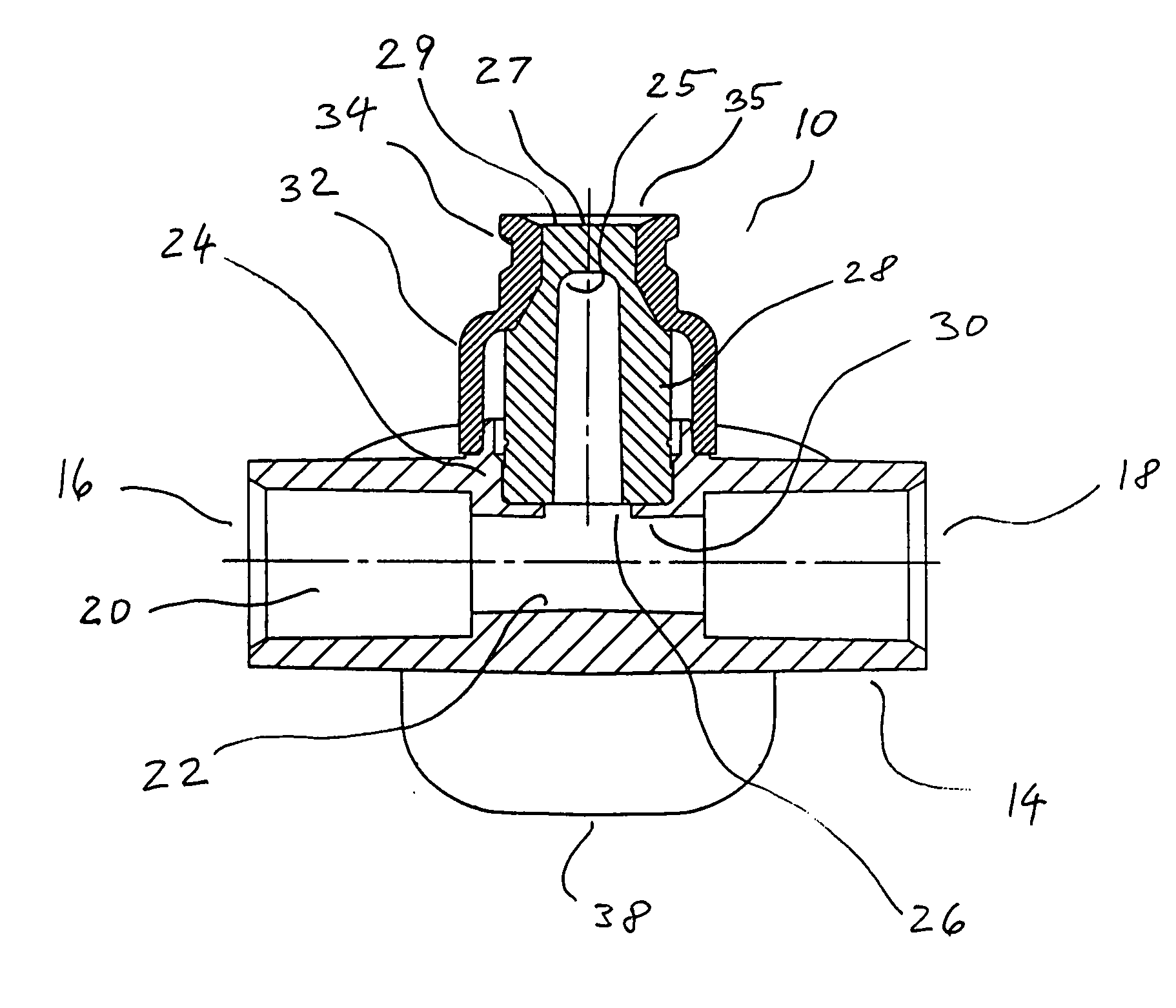
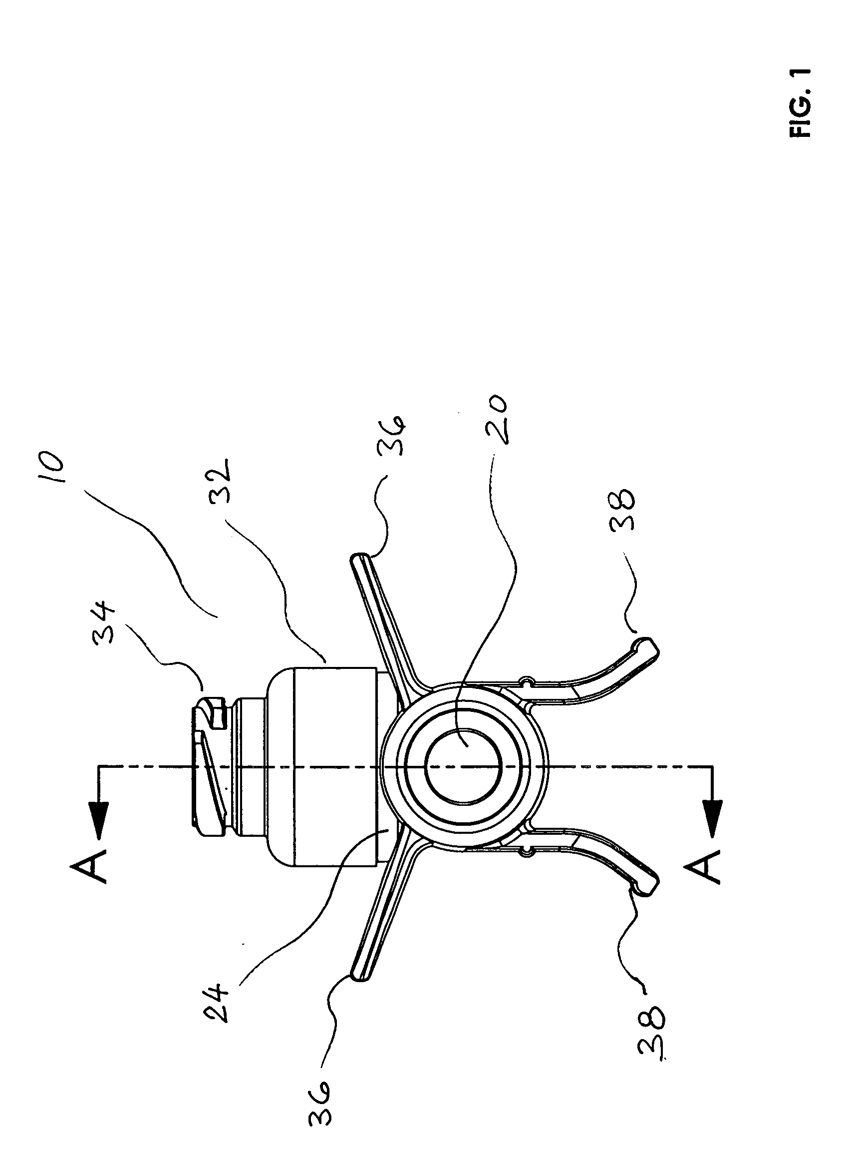
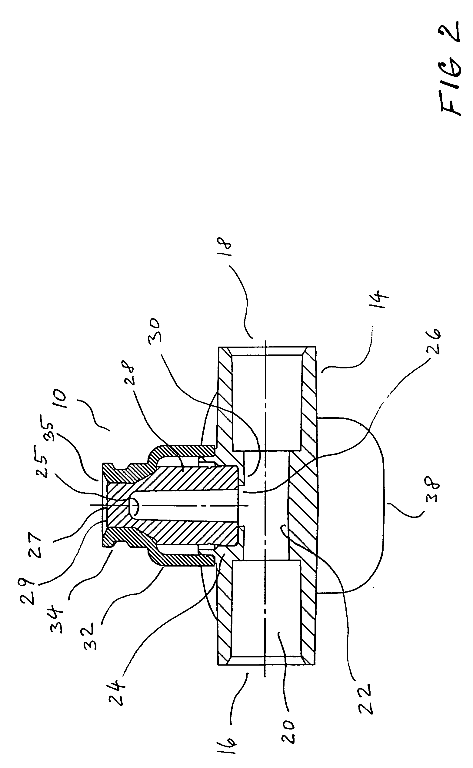
[0030] As shown in FIG. 4, the T-port valve 10 of the invention is configured for connection in-line with a length of medical tubing 12. As best shown in FIG. 2, the T-port site 10 of the invention comprises a longitudinal tubular port body 14 having opposing ends 16 and 18. A longitudinal bore 20 extends longitudinally through the port body 14 to fluidly interconnect the ends 16 and 18. The ends 16 and 18 are configured, preferably circular-cylindrically, to sealingly receive the ends of the tubing 12. The longitudinal bore 20 may include a reduced diameter portion 22 in the middle portion of the port body 14 to serve as a stop for the ends of the tubing 12 and to provide an increased wall thickness at such middle portion to which is integrally formed a transverse valve portion 24. A bore 26 extends through the valve portion 24 to be in fluid communication with the bore 20 of the tubular port body 14.

[0031] A valve stem 28 is positioned concentrically within the valve portion 24 a...


PUM


Abstract

A slit-type T-port site that includes a swabbable valve with a slit at an end thereof. The valve stem with a slit is located in a valve body and is deformable. When engaged by a tip of an instrument, the top portion of the stem folds inward and its slit opens to form a direct non-hemolytic flow pathway between the instrument and the main T-port site flow channel.

Description

CROSS-REFERENCE TO RELATED APPLICATIONS [0001] This application claims the benefit of provisional application No. 60 / 573,671, filed May 21, 2004, the disclosure of which is incorporated by reference herein.BACKGROUND OF THE INVENTION [0002] 1. Field of the Invention [0003] This invention relates to valves. More particularly, this invention relates to swabbable valves used in the medical industry. [0004] 2. Description of the Background Art [0005] As the term implies, the term “swabbable” is often used in conjunction with medical valves having a female luer fitting configured in such a way that allows swabbing of the exposed portion of the valve just prior to connection with a male luer needleless syringe or other device. [0006] Representative swabbable valves are disclosed in U.S. Pat. Nos. 6,036,171, 6,692,478, 6,221,065, 6,168,137, 6,117,114, 6,651,956, 6,113,068 and RE 37,357, the disclosures of which are hereby incorporated by reference herein. [0007] As taught by the above-refe...

Claims


Application Information

Patent Timeline
Patent Type & Authority Applications(United States)
IPC IPC(8): A61M5/14A61M39/04A61M39/16A61M39/26
CPCA61M39/045A61M39/26A61M39/16
Inventor MILLER, PAVEL T.
Owner HALKEY ROBERTS CORP
Why Eureka
Try Eureka