Carrying handle of luggage

Inactive Publication Date: 2005-12-01
SHER YUH YI
View PDF5 Cites 10 Cited by
  • Summary
  • Abstract
  • Description
  • Claims
  • Application Information

AI Technical Summary

Benefits of technology

[0009] In a preferred embodiment of the present invention, the abutment plate and the cover can be used in different color so as to obviously and readily demonstrate the colorful logo projected from the top of the cover at one time injection molding w

Problems solved by technology

But this is unsatisfactory for the purpose of which the invention is concerned for the following reasons: The exposed heads of the rivets R are not aesthetic.
Also, it is difficult or even impossible of forming or printing a logo or the like on a top of the end units B. Another conventional carrying handle

Method used


Image

  • Carrying handle of luggage
  • Carrying handle of luggage
  • Carrying handle of luggage

Examples


Example

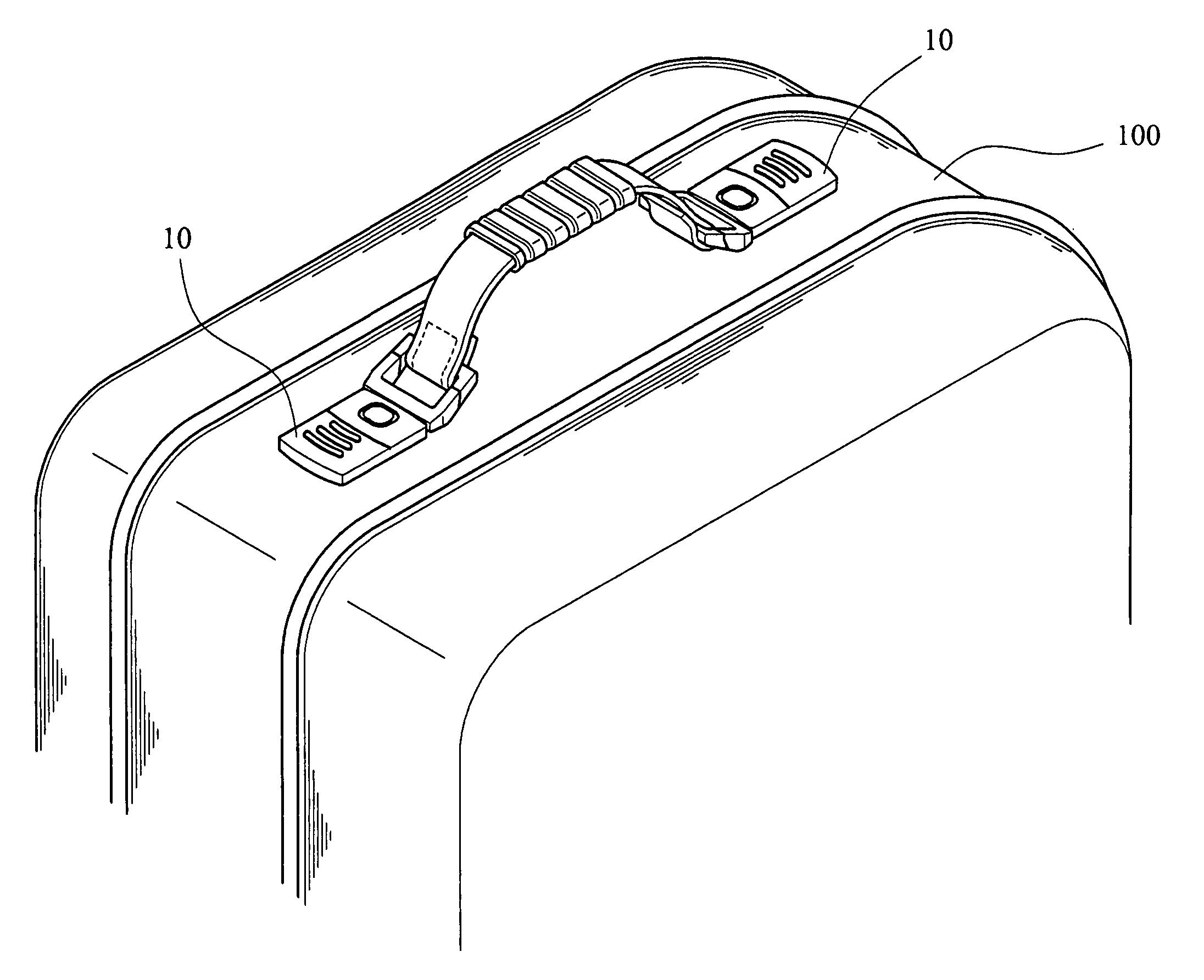
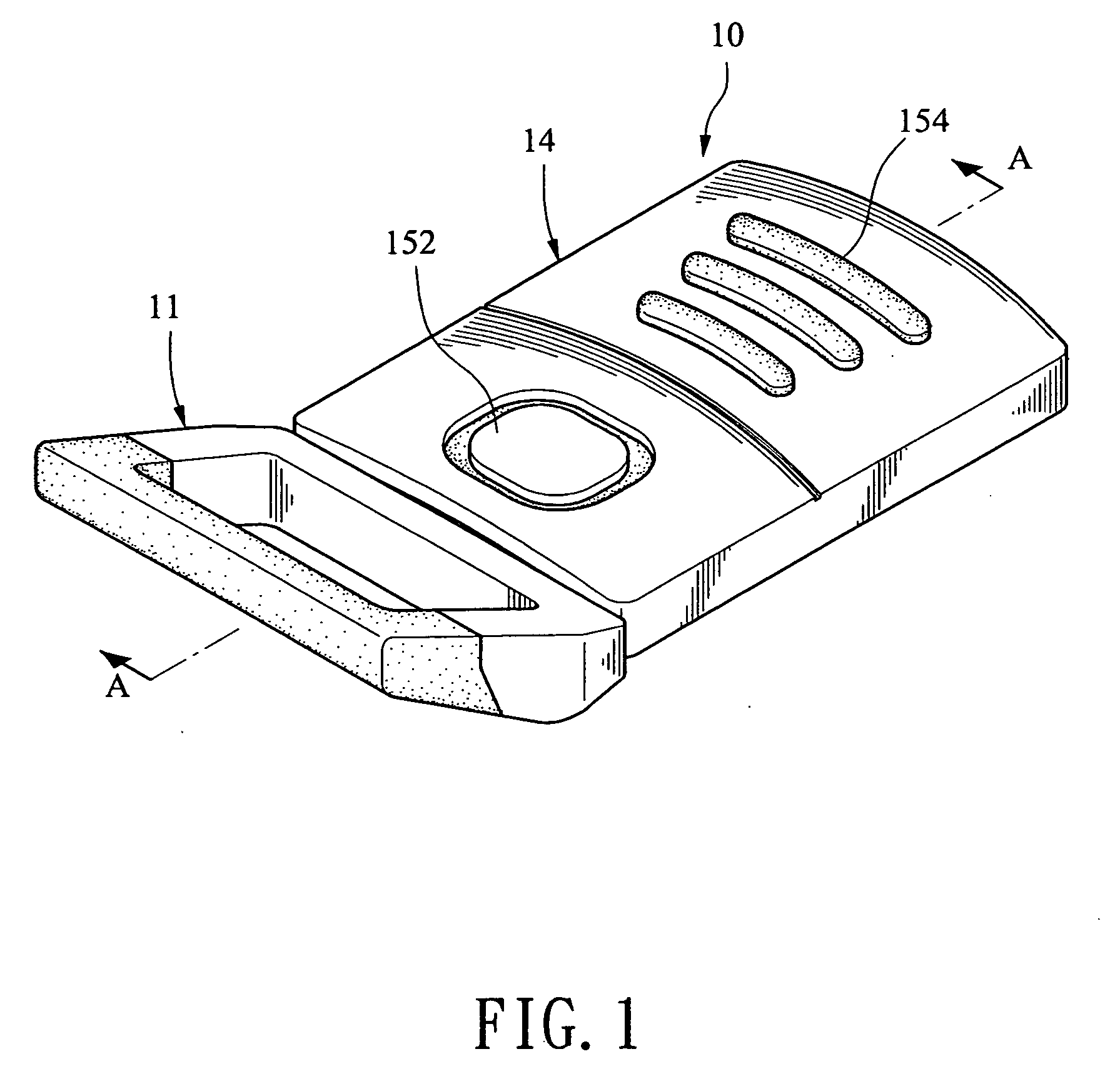
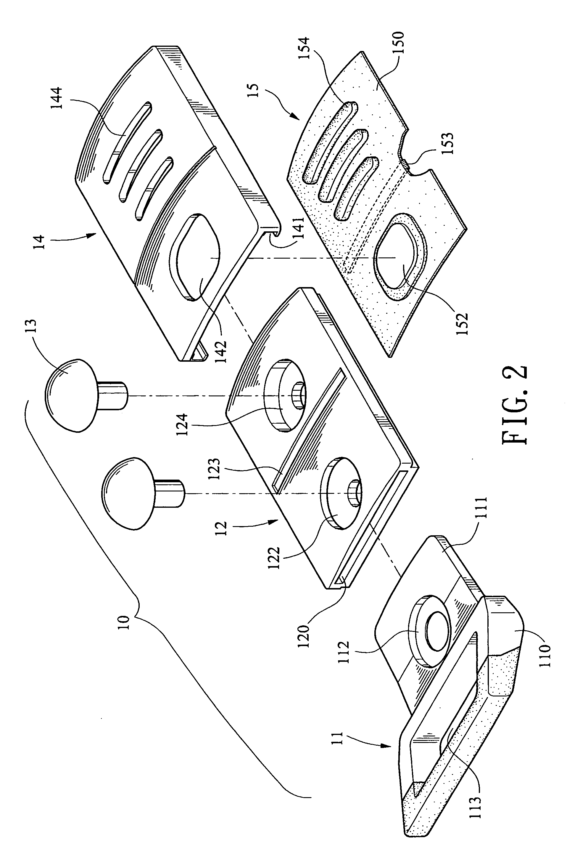
[0019] Referring to FIGS. 1 to 5, there is shown a carrying handle having two end units 10 mounted on a top of luggage 100 in accordance with the invention. Either end unit 10 comprises a joining member 11, a body 12, a cover 14, and an abutment plate 15. Each component will be described in detail below.

[0020] The joining member 11 is formed of metal (e.g., zinc alloy, copper and aluminium alloy, or the like) and comprises an upwardly inclined loop 110 for enclosing a rectangular opening 113 with strap looped around, and a horizontal section 111 having a staged hole 112. The rectangular, flat body 12 has a section of substantial “T” and is formed of plastic material. The body 12 comprises a slot 120 at one end for receiving the horizontal section 111, a first staged hole 122 penetrated the slot 120, the hole 122 being aligned with the hole 112 so that a rivet 13 is able to drive through both the holes 122 and 112 into the luggage 100 for fastening, a widthwise groove 123 in about c...


PUM


Abstract

Either end unit of carrying handle of luggage comprises a joining member including a horizontal section having a first hole, a body including a slot for receiving the horizontal section, a second hole penetrated the slot so that a rivet is driven through the aligned first and second holes into the luggage, a widthwise groove, and a third hole so that another rivet is driven through the third hole into the luggage, an abutment plate including an upward projection, a widthwise protrusion on a bottom, the protrusion being fitted into the groove for holding the abutment plate on the body in place, and widthwise ridges, and a cover including an opening and widthwise slits. The cover is slid onto the body until being stopped by the joining member for covering the rivet with the projection exposed from the opening and the ridges projected from the slits for fastening.

Description

BACKGROUND OF THE INVENTION [0001] 1. Field of the Invention [0002] The present invention relates to carrying handle of luggage and more particularly to such a carrying handle having improved end units joined a luggage shell. [0003] 2. Description of Related Art [0004] A conventional carrying handle of luggage comprises two end units B joined a top of luggage L by two rivets R as shown in FIG. 6. But this is unsatisfactory for the purpose of which the invention is concerned for the following reasons: The exposed heads of the rivets R are not aesthetic. Also, it is difficult or even impossible of forming or printing a logo or the like on a top of the end units B. Another conventional carrying handle of luggage is shown in FIG. 7. It can overcome the above drawbacks of being unaesthetic and difficult or impossible of forming or printing a logo on the end units B. However, the logo may be obscured by rubbing after a period of time of use. Moreover, the threaded securing of the end unit...

Claims


Application Information

Patent Timeline
IPC IPC(8): A45C13/26A45C13/30A47B95/02
CPCY10T16/455A45C13/26
Inventor SHER, YUH YI
Owner SHER YUH YI
Why Eureka
Try Eureka