
Sensor element of a gas sensor

Inactive Publication Date: 2005-11-22
ROBERT BOSCH GMBH
View PDF9 Cites 4 Cited by
  • Summary
  • Abstract
  • Description
  • Claims
  • Application Information

AI Technical Summary

Benefits of technology

[0005]The sensor element according to the present invention is distinguished by its comparatively simple design and by the fact that all pumping electrodes are located in the internal gas spaces of the sensor element. This permits low-cost manufacture of the sensor element and, at the same time, a long service life for the pumping electrodes that are used. The simple design is achieved by locating the outer pumping electrode in a separate internal gas space of the sensor element, the gas space being integrated into a layer plane of the sensor element in which another internal gas space of the sensor element or a reference gas duct is already located.
[0006]Advantageous refinements of and improvements on the sensor element are possible. For example, the internal gas space in which the outer pumping electrode is located may be in contact with a reference gas atmosphere and thus all contact with the corrosive gas mixture atmosphere may be prevented. In another especially advantageous embodiment, the internal gas space in which the outer pumping electrode is located is in contact with the ambient air via a porous electrode lead. This permits a favorable geometry of the internal gas space in which the outer pumping electrode is located and, simultaneously, adequate ventilation of the internal gas space.

Problems solved by technology

Although this outer pumping electrode is frequently provided with a porous protective coating, it is nonetheless exposed to the corrosive effects of the hot combustion exhaust gases.
This sensor element design is complex, however, and therefore cost-intensive.

Method used


Image

  • Sensor element of a gas sensor
  • Sensor element of a gas sensor
  • Sensor element of a gas sensor

Examples


first embodiment

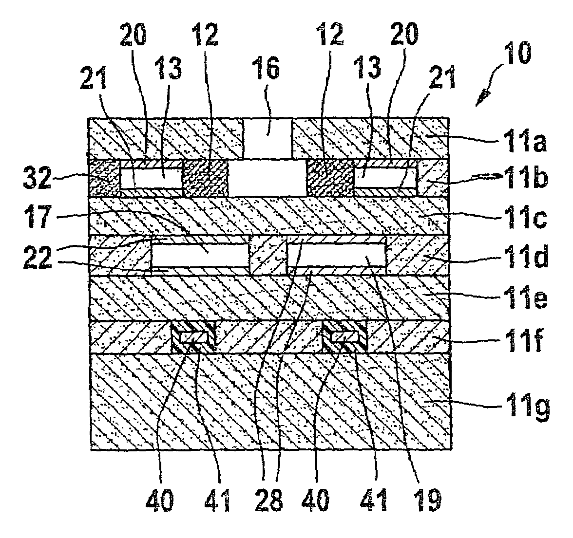
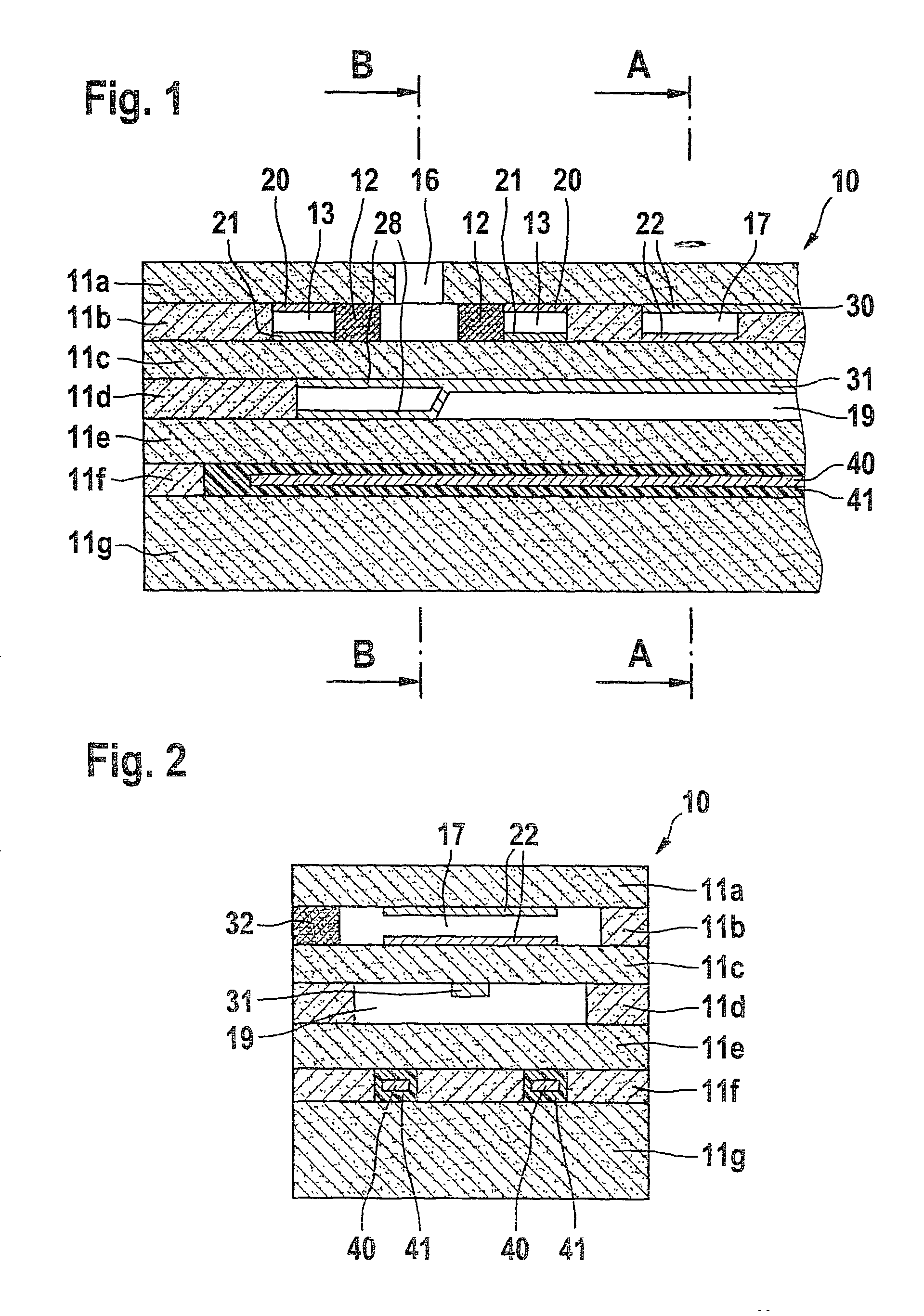
[0013]FIG. 1 shows a basic structure of the present invention. A planar sensor element of an electrochemical gas sensor is designated as 10, the element having a plurality of oxygen ion-conducting solid electrolyte layers 11a, 11b, 11c, 11d, 11e, 11f and 11g, for example. In this case, solid electrolyte layers 11a to 11g are designed as ceramic sheets and form a planar ceramic body. They are composed of an oxygen-ion-conducting solid electrolyte material such as ZrO2 that has been stabilized or partially stabilized with Y2O3.

[0014]The integrated form of the planar ceramic body of sensor element 10 is manufactured by laminating together ceramic sheets imprinted with functional layers and then sintering the laminated structure by a method that is known per se.

[0015]Sensor element 10 includes two gas spaces, an internal gas space 13 and a reference gas duct 19. Reference gas duct 19 is open at one end and is in contact with a reference gas atmosphere. Internal gas space 13 is annular i...

second embodiment

[0023]FIG. 3 illustrates a cross section through a sensor element shown in FIG. 1 along section plane B—B according to the present invention. In this embodiment, the second internal gas space 17 is incorporated into layer plane 11d, in which reference gas duct 19 is also located. Second internal gas space 17 is aligned parallel to reference gas duct 19, and like the latter it is in contact with a reference gas atmosphere. This design corresponds to a double reference gas duct that is divided in its longitudinal direction.

third embodiment

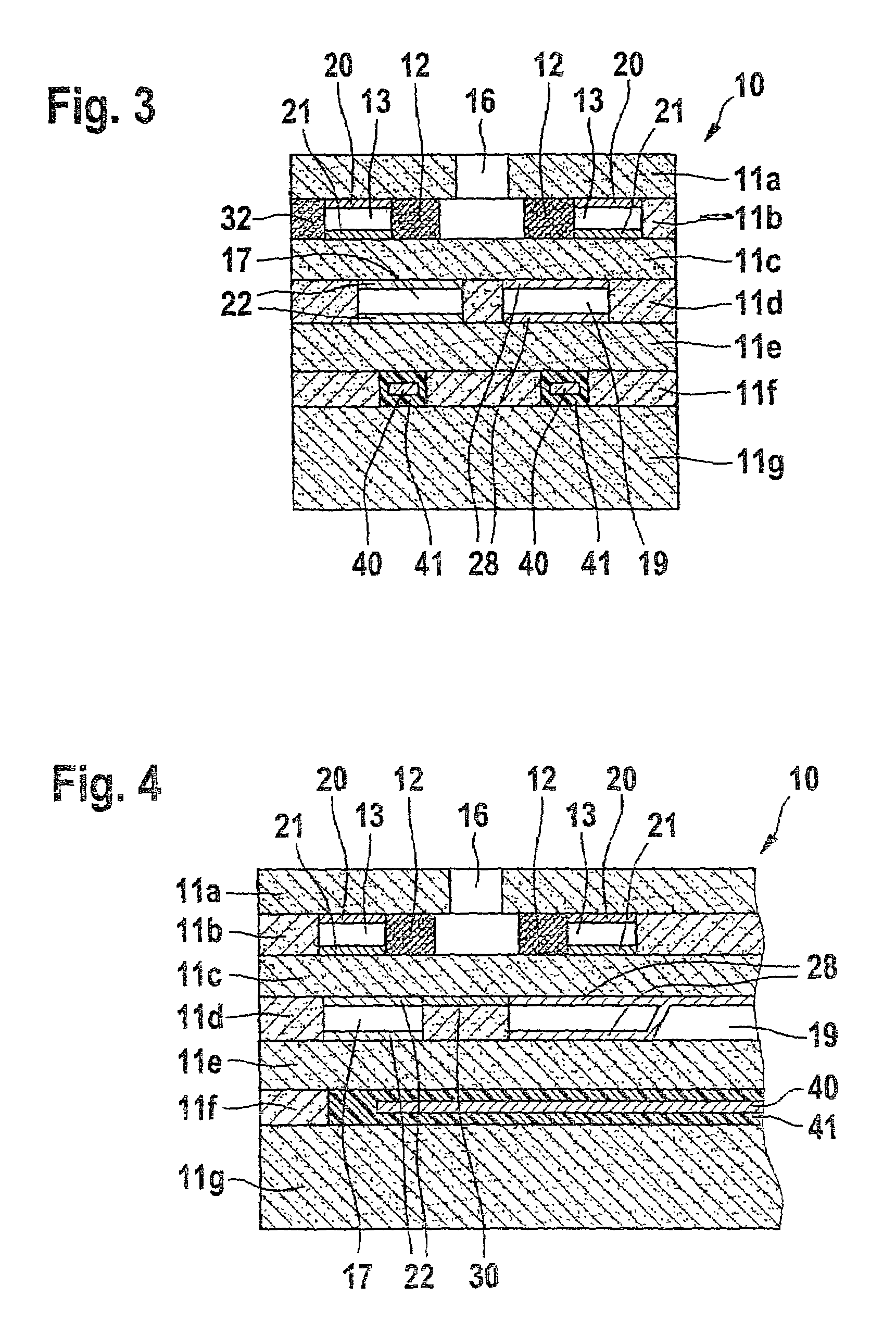
[0024]FIG. 4 shows a sensor element according to the present invention as a variant of the sensor element illustrated in FIG. 3.

[0025]Second internal gas space 17, which includes outer pumping electrode 22, is located in layer plane 11d, in which reference gas duct 19 is located. In this embodiment, second internal gas space 17 is not designed in the form of a separate reference gas duct but as a gas space having no direct contact with a reference gas atmosphere. In order to prevent potential overpressure during operation of the sensor element, second internal gas space 17, as already described in the case of the sensor element shown in FIG. 2, may be vented via another diffusion barrier or a porous lead of electrode 22.

[0026]Whereas FIGS. 1 through 4 describe and show examples of sensor elements for determining the oxygen concentration of a gas mixture, FIGS. 5 and 6 illustrate sensor elements that are used for the determination of nitrogen oxides, for example.


PUM


Abstract

A solid electrolyte-based sensor element of a gas sensor for determining a gas component in a gas mixture is described, in particular for determining the concentration of oxygen and / or nitrogen oxides in exhaust gases of internal combustion engines. The sensor element has an electrochemical cell that includes a first and a second electrode, both electrodes being located in internal gas spaces of the sensor element. The internal gas space in which the first electrode is located is largely in the same layer plane of the sensor element as at least one other internal gas space of the sensor element in which the second electrode or a reference electrode are located.

Description

FIELD OF THE INVENTION[0001]The present invention concerns a sensor element of a gas sensor for determining the concentration of a gas component in a gas mixture.BACKGROUND INFORMATION[0002]Solid electrolyte-based gas sensors, by which the concentration of individual gas components can be determined electrochemically, have been used for some time in the analysis of exhaust gases of internal combustion engines. The mode of operation of some of these gas sensors is based on the fact that the oxygen concentration within one sensor element integrated into the gas sensor is set at a constantly low value. This is accomplished by an electrochemical pumping process in which oxygen transfer takes place between the electrodes of an electrochemical pumping cell. One of the electrodes of the pumping cell is located on the sensor element's outer surface that is exposed to the exhaust gas. Although this outer pumping electrode is frequently provided with a porous protective coating, it is nonethe...

Claims


Application Information

Patent Timeline
IPC IPC(8): G01N27/417G01N27/419G01N27/416
CPCG01N27/419
Inventor KETTERLE, KARL-MICHAELSCHUMANN, BERND
Owner ROBERT BOSCH GMBH
Learn More