Impulse Centrifuge for the Purification of the Lubricating Oil from an Internal Combustion Engine
- Summary
- Abstract
- Description
- Claims
- Application Information
AI Technical Summary
Benefits of technology
Problems solved by technology
Method used
Image
Examples
Embodiment Construction
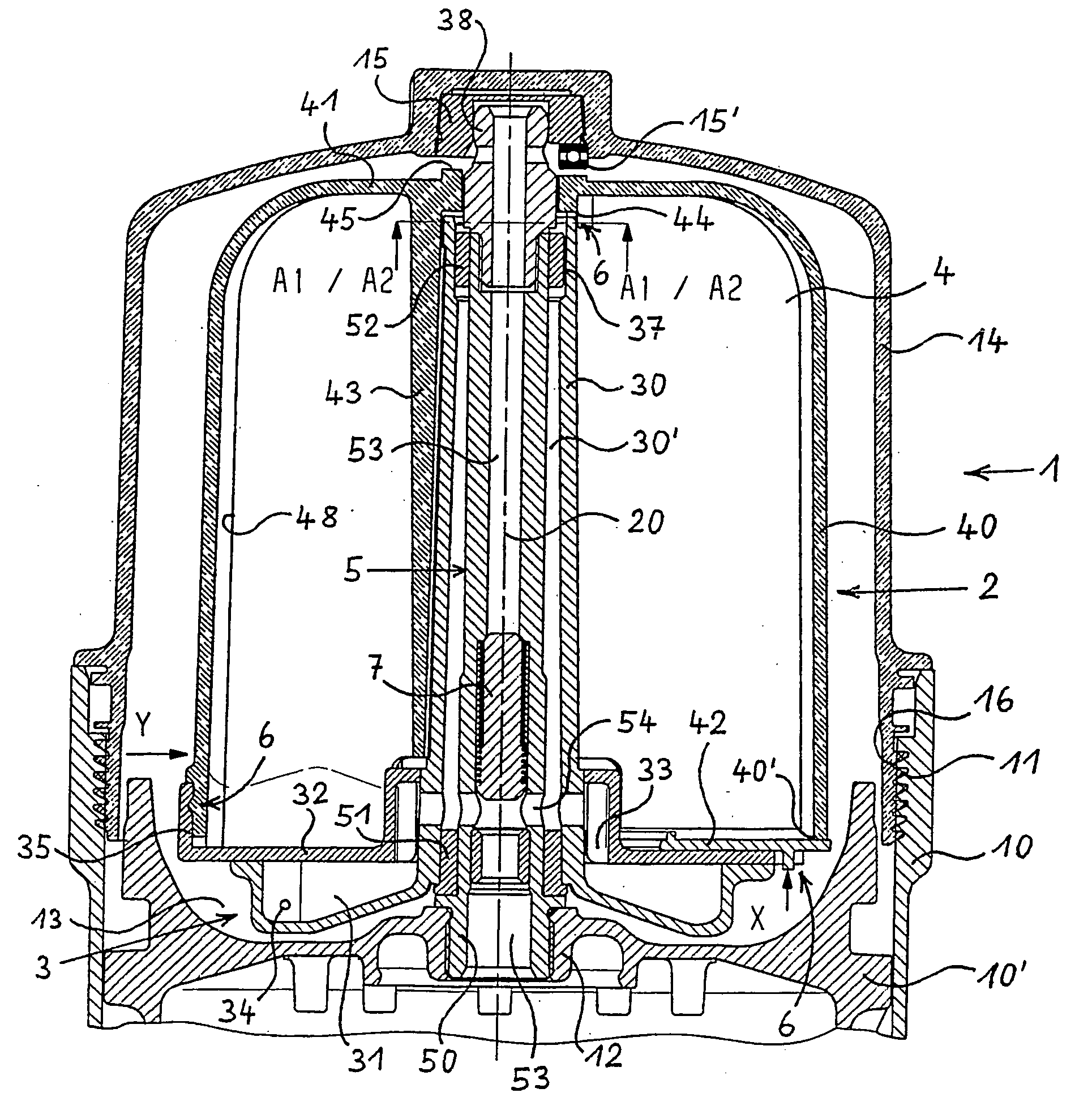
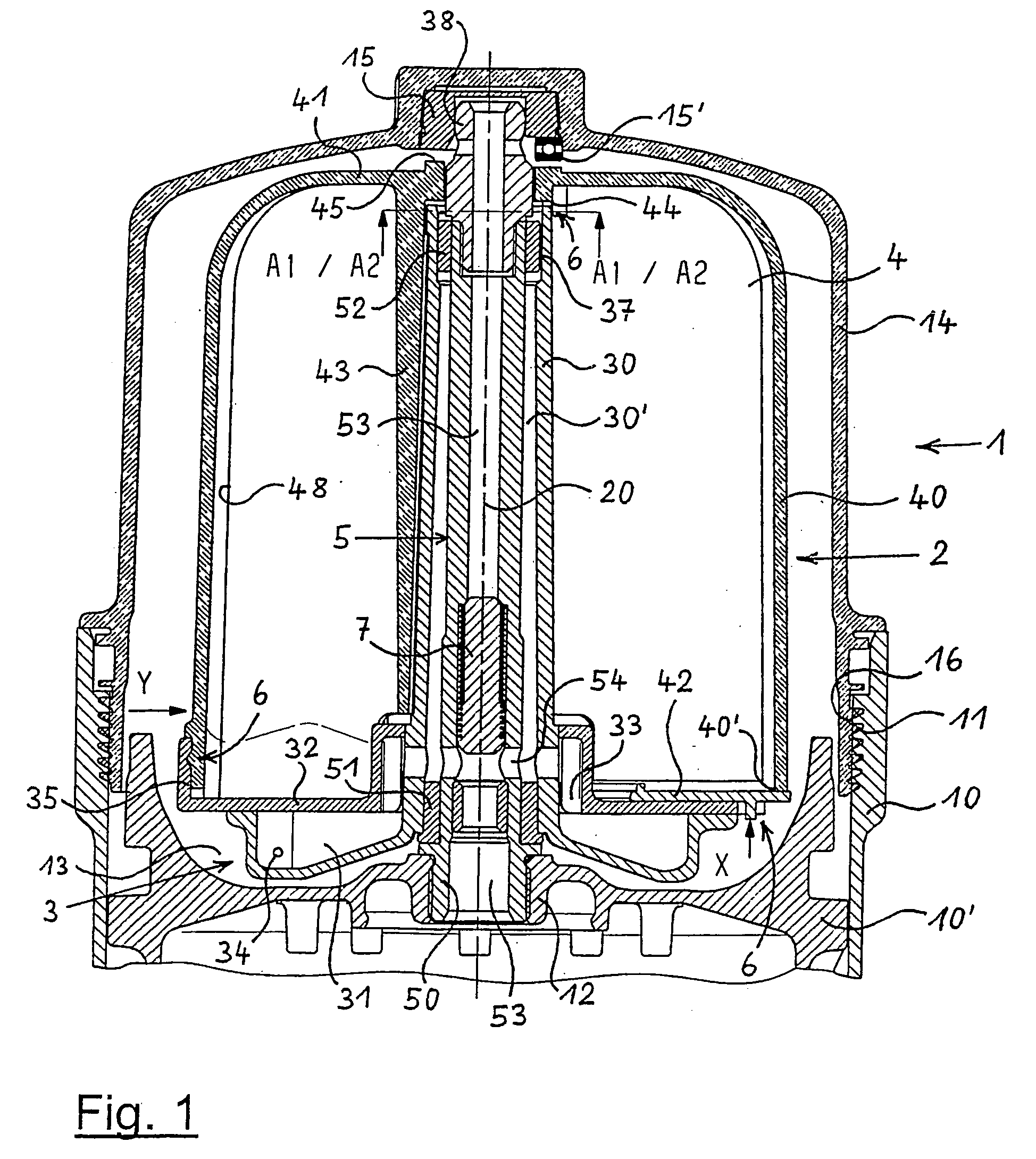
[0162]The free-jet centrifuge 1 shown in FIG. 1 comprises a housing 10 which is closed on the upper side with a screwed cover 14. In housing 10, a housing part 10′ is provided and fixed which carries an axis 5. On the axis 5, a rotor 2 is rotatably provided on bearings. For the detachable connection between housing 10 and cover 14, the housing 10 has an internal thread 11 and the cover 14 an external thread 16.
[0163]The housing part 10′ provided in housing 10 has in its center an axis receiver 12 with an internal thread into which one threaded end 50 of the axis 5 is screwed in. The axis 5 extends upwardly through the entire rotor 2 up to the inside of cover 14. In its interior, axis 5 is hollow in design and comprises a central channel 53 there. Through channel 53, the lubricating oil to be cleaned is fed to the rotor 2. From the lower area of the central channel 53, two radial channels 54 branch off which lead via branching channels 33 within a nozzle bearing body 31 to two nozzle...
PUM
| Property | Measurement | Unit |
|---|---|---|
| Fraction | aaaaa | aaaaa |
| Fraction | aaaaa | aaaaa |
| Weight | aaaaa | aaaaa |
Abstract
Description
Claims
Application Information
 - R&D
- Intellectual Property
- Life Sciences
- Materials
- Tech Scout
- Unparalleled Data Quality
- Higher Quality Content
- 60% Fewer Hallucinations
Browse by: Latest US Patents, China's latest patents, Technical Efficacy Thesaurus, Application Domain, Technology Topic, Popular Technical Reports.
© 2025 PatSnap. All rights reserved.Legal|Privacy policy|Modern Slavery Act Transparency Statement|Sitemap|About US| Contact US: help@patsnap.com


