
Tandem axle suspension assembly

a technology of axle suspension and axle, which is applied in the direction of suspensions, vehicle components, transportation and packaging, etc., can solve the problems of air spring suspension providing relatively harsh ride characteristics, air spring suspension system being more expensive than a comparable leaf spring suspension, etc., to achieve favorable loading dock performance, favorable ride characteristics, and favorable ride characteristics

Inactive Publication Date: 2005-12-01
ARVINMERITOR TECH +1
View PDF20 Cites 12 Cited by
  • Summary
  • Abstract
  • Description
  • Claims
  • Application Information

AI Technical Summary

Benefits of technology

[0007] An air spring assembly is mounted between the axle and the vehicle frame to provide desirable ride characteristics. The control rod includes a first connection to the vehicle frame and a second connection to the axle. The control rod constrains longitudinal and vertical movement of the axle. The spring member is rigidly attached to the axle to counteract forces that can cause roll movements of the vehicle. The rigidly mounted spring member exerts torsion forces on the axle to counter roll forces while the air spring assemblies provide favorable ride characteristics adaptable to various trailer load conditions.
[0008] Accordingly, the suspension assembly of this invention provides favorable loading dock performance and favorable ride characteristics without additional add on devices.

Problems solved by technology

However, the leaf spring suspension may provide relatively harsh ride characteristics during unloaded or lightly loaded conditions.
Disadvantageously, an air suspension system may be more expensive than a comparable leaf spring suspension.
Air spring suspension systems may also not provide optimal loading dock performance due to height variations between loaded and unloaded conditions.
Such devices typically require manual operation before, during and after the loading process.
As appreciated, these mechanical add on devices increase weight, expense, and maintenance requirements.

Method used


Image

  • Tandem axle suspension assembly
  • Tandem axle suspension assembly
  • Tandem axle suspension assembly

Examples


Embodiment Construction

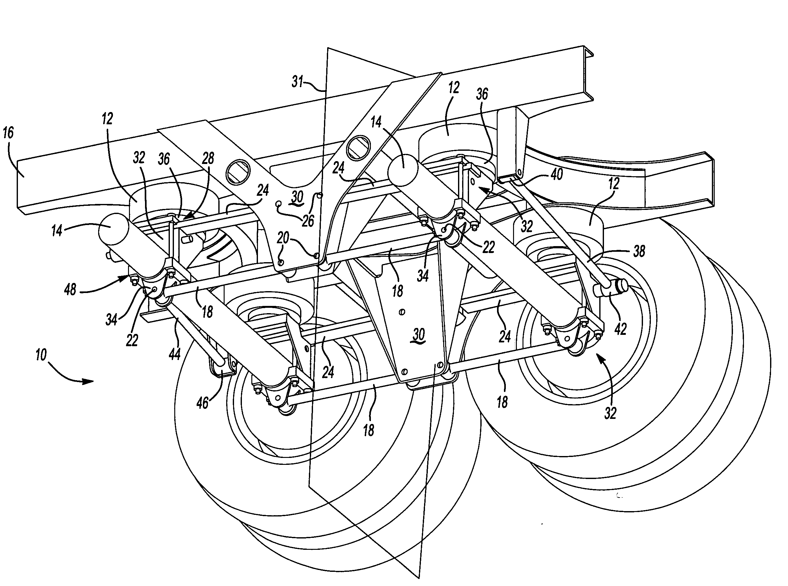
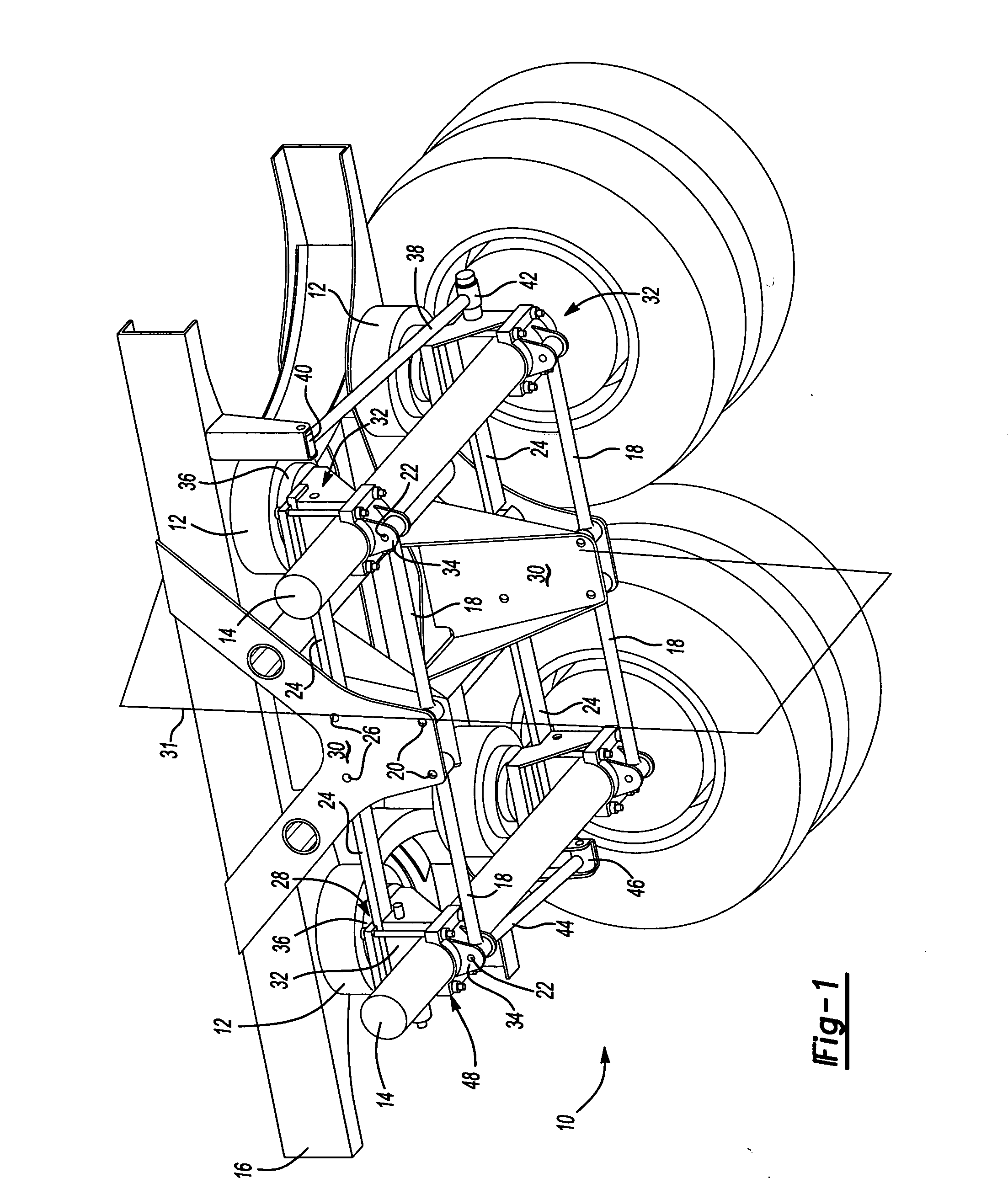
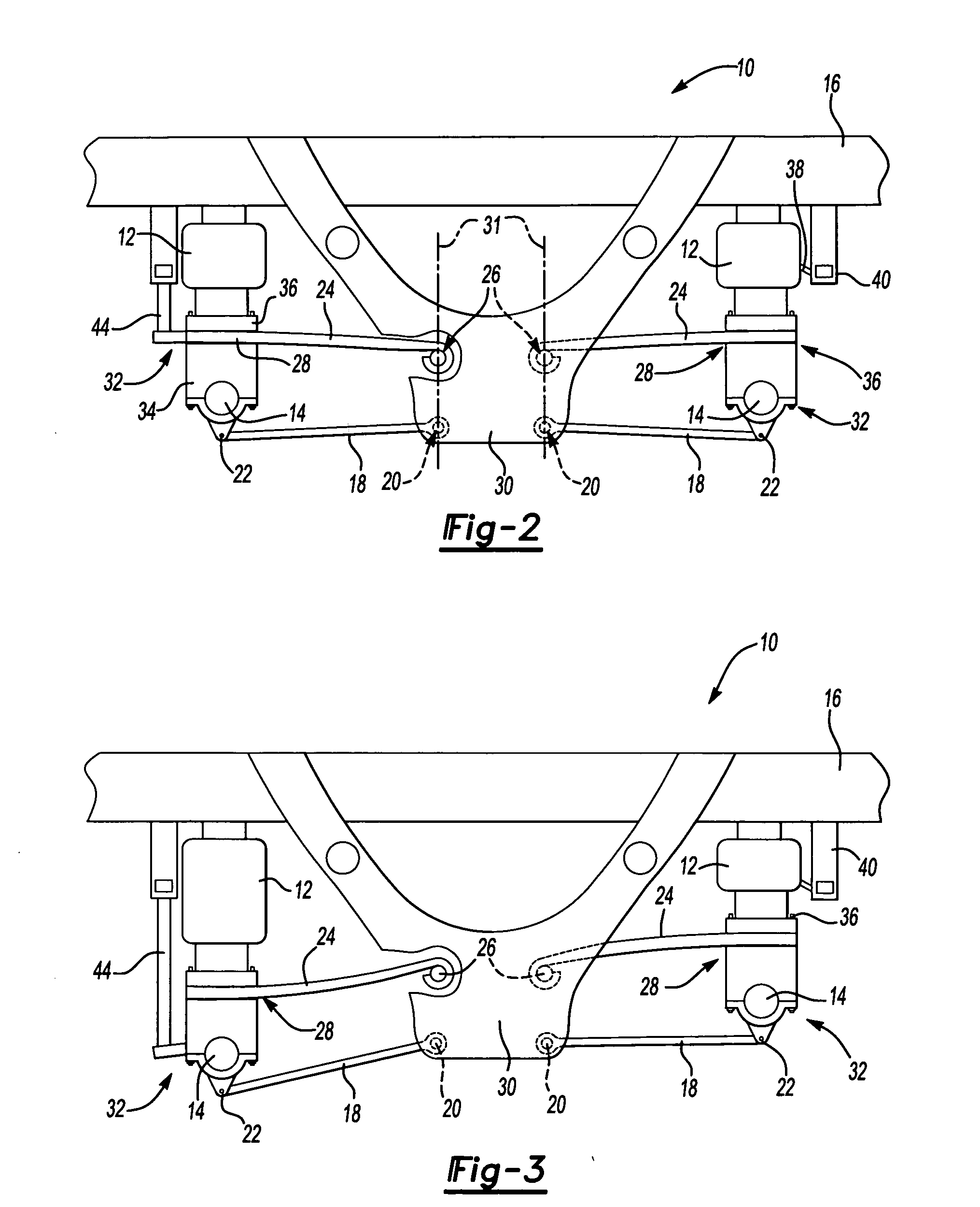
[0016] Referring to FIGS. 1 and 2, a tandem axle suspension assembly 10 includes a pair of axles 14, each supported by an air spring assembly 12 relative to a frame 16. Preferably, the suspension assembly 10 supports axles 14 that are not driven such as are commonly used for cargo trailers, however, a driven axle system may also benefit from the suspension assembly 10 of this invention.

[0017] A control rod 18 includes a pivotal connection 20 to a fixed link plate 30 that is rigidly attached to the frame 16. The control rod 18 includes a pivotal connection 22 to an axle mount 32 supporting one of the axles 14. The control rod 18 constrains longitudinal and vertical movement of the axles 14 relative to the frame 16.

[0018] A spring member 24 includes a pivotal connection 26 to the link plate 30 and fixed connection 28 to the axle mount 32 below the air spring assembly 12. Preferably, the spring member 24 is a leaf spring having a desired thickness, however, the spring member 24 can a...


PUM


Abstract

A vehicle suspension assembly includes a control rod pivotally connected between a vehicle frame and an axle. The control rod controls longitudinal and vertical movement of the axle. A spring member is pivotally connected to the frame and fixed to the axle. Air spring assemblies are mounted between the axle and frame. The rigidly mounted spring member exerts torsion forces on the axle to counter roll forces and the air spring assemblies provide favorable ride characteristics adaptable to various trailer load conditions.

Description

BACKGROUND OF THE INVENTION [0001] This invention generally relates to a tandem axle suspension assembly, and more specifically to a walking beam tandem axle suspension assembly. [0002] Typically, vehicles such as cargo trailers include a steel leaf spring for suspending an axle from a vehicle frame. The steel leaf spring suspension requires little maintenance and provides favorable loading dock performance. The favorable dock performance results from a relatively small amount of vertical displacement between loaded and unloaded conditions of the leaf spring suspension. However, the leaf spring suspension may provide relatively harsh ride characteristics during unloaded or lightly loaded conditions. [0003] Another trailer suspension utilizes air springs for each axle. The air springs provide favorable ride characteristics regardless of the load on the trailer. Further, specific ride characteristics can be tailored to a specific load and desired handling characteristics. [0004] Disad...

Claims


Application Information

Patent Timeline
Patent Type & Authority Applications(United States)
IPC IPC(8): B60G5/00
CPCB60G5/047B60G9/003B60G2200/31B60G11/465B60G9/006
Inventor MILLER, STEVEN R.REYNOLDS, MARK P.ECKELBERRY, JAMESCARLSTEDT, ROBERT P.CHIEN, DANIEL G.LANG, KENNETH G.PEAKER, MARTINSAXON, NANCY L.TIMMERMANS, JOSLLOYD, JEFF
Owner ARVINMERITOR TECH
Learn More