Variable beam LED light source system

a technology of led light source and variable beam, which is applied in the direction of lighting support devices, lighting combinations, lighting applications, etc., can solve the problems of mr and par lamps being fixed focus, unable to adapt to control beam angles, and wasting 90 percent or more light energy

Inactive Publication Date: 2005-12-01
ALTMAN STAGE LIGHTING
View PDF6 Cites 147 Cited by
  • Summary
  • Abstract
  • Description
  • Claims
  • Application Information

AI Technical Summary

Benefits of technology

[0026] It is a further object of the present invention to provide a lighting system that is capable of selectively varying the common directional angles of a plurality of individual LED arrays arranged around a common central axis;
[0027] It is still a further object of the present invention to provide a lighting system that is capable of simultaneously and selectively moving a plurality of individual LED arrays about a common central axis to as to collectively arrange the totality

Problems solved by technology

Such a system results in 90 percent or more of the light energy wasted by the incandescent filament lamp.
Incandescent filament lamps are capable of generating high-intensity light for only a relatively short period of time and in addition are very susceptible to damage from both shock and vibration.
MR and PAR lamps are fixed focus and are not adapted to control beam angles.
LED technology to date does not offer complete control of output beam angles.
Also, permanent molding of the light emitting elements seems necessary, which indicates a difficulty in replacing the elements when they fail.
The number of elements is limited primarily by the fact that the flexible membrane can support a restricted numbe

Method used


Image

  • Variable beam LED light source system
  • Variable beam LED light source system
  • Variable beam LED light source system

Examples


embodiment 62

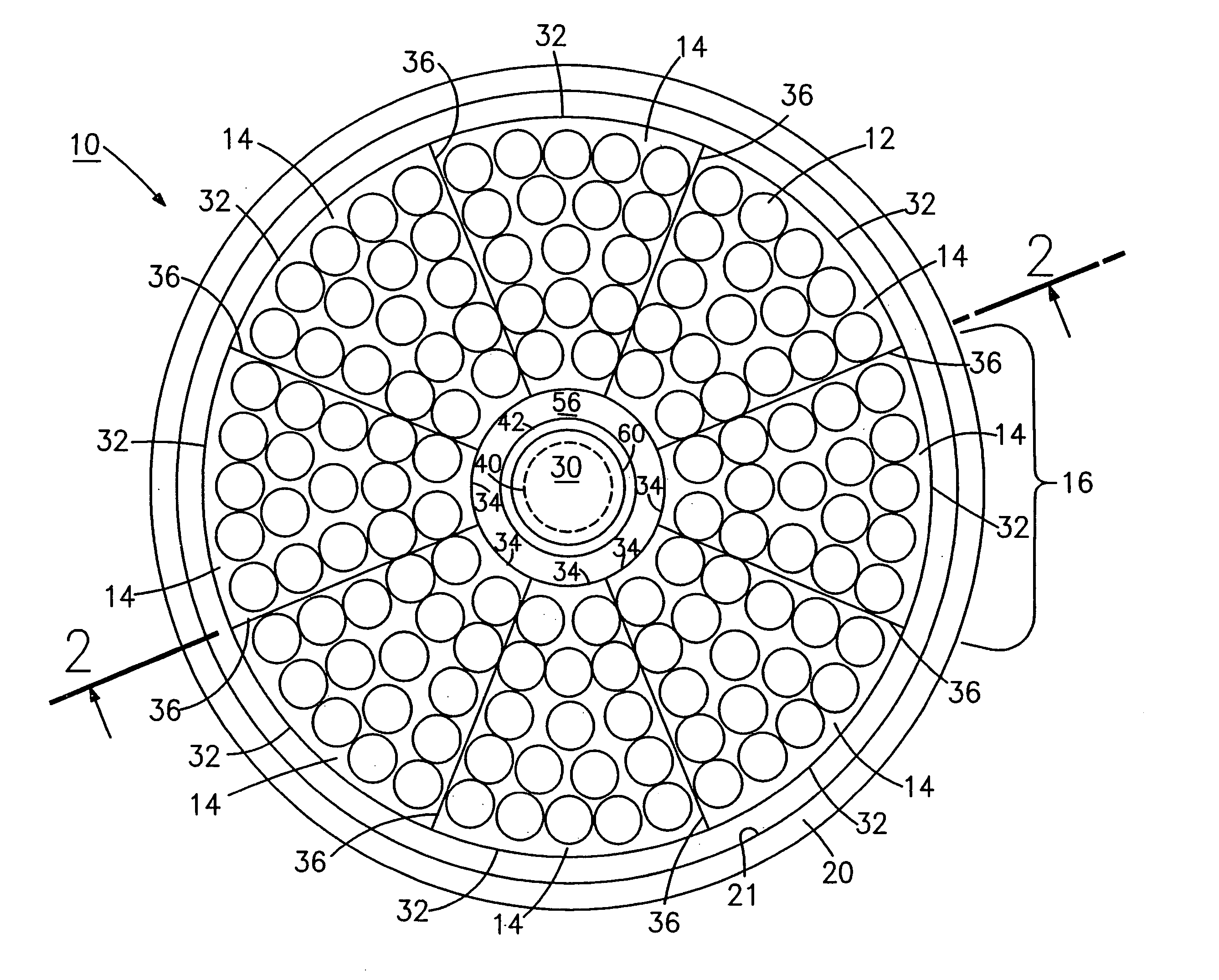
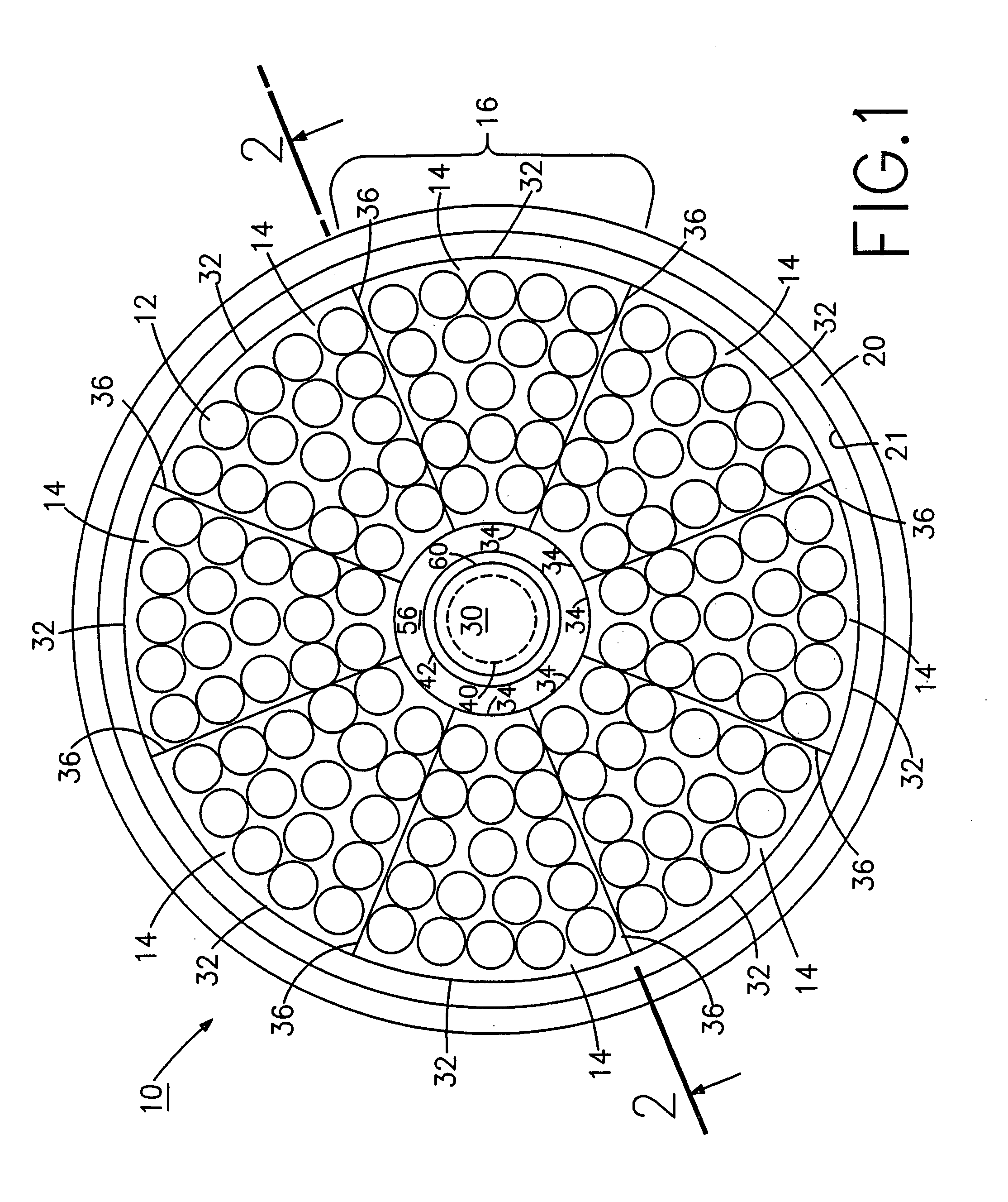
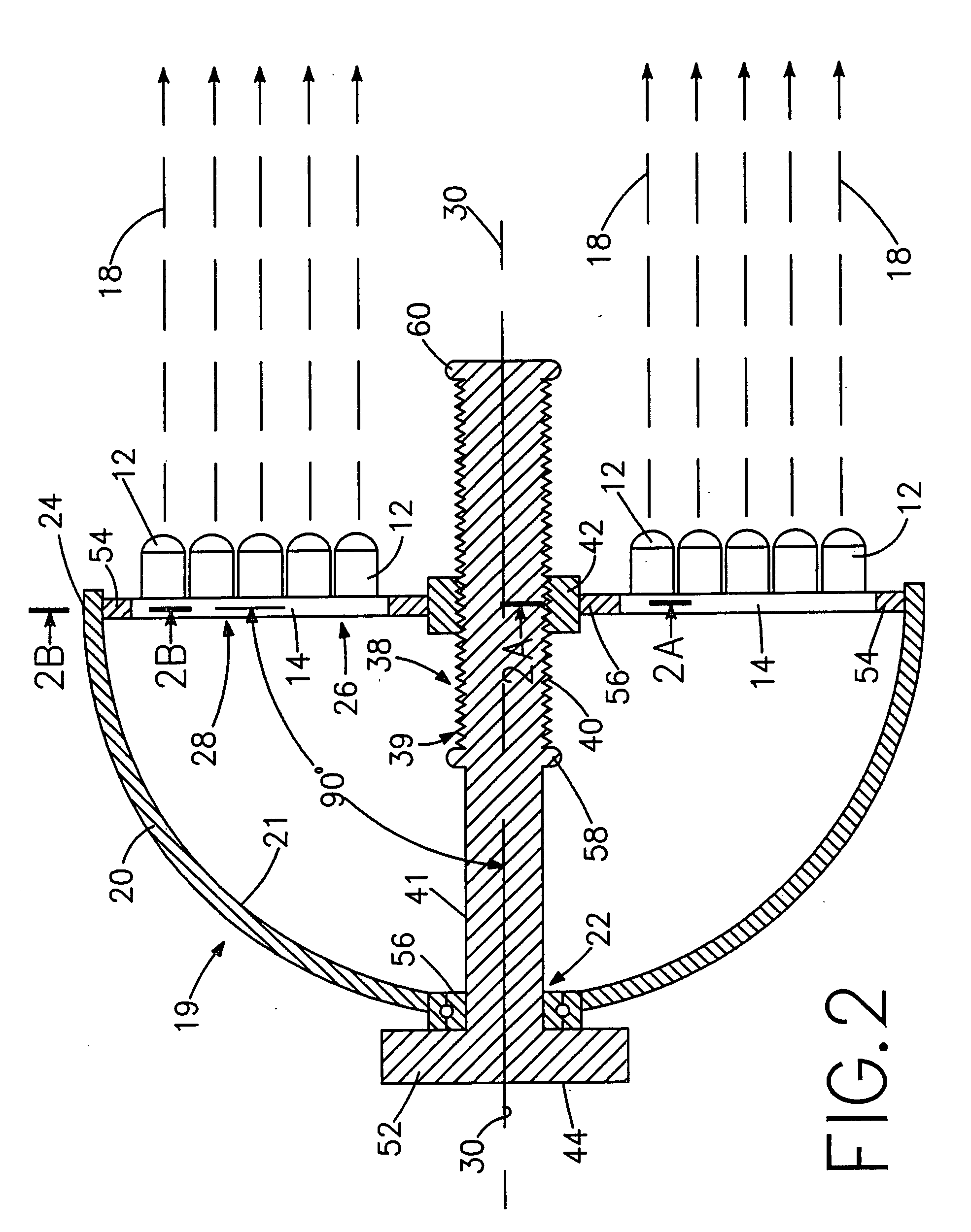
[0074]FIG. 6 shows a diode lighting system embodiment 62 generally analogous to diode lighting system 10 that includes housing 19 with the circular housing rim 24 defining circular aperture 26 and diodes 12 mounted to eight diode panels 14. Screw arrangement 38 including externally threaded solid cylinder 40 having opposed inner and outer end portions 44 and 46, respectively, and internally threaded cylindrical nut 42 threaded thereto is mounted in housing 19 at inner end portion 44 in alignment with a central housing axis 30. An optional handwheel 64 is positioned external to housing 19 at inner end portion 44. Eight diode panels 14 having diodes 12 mounted thereto are connected to housing 19 at circular housing rim 24 exactly as shown in FIGS. 1 and 2. Flexible internal and outer connecting rings 54 and 56, respectively, connect diode panels 14 to cylindrical nut 42 as shown in FIGS. 1 and 2. Internal and external stops 58 and 60, respectively, are mounted to externally threaded c...

embodiment 142

[0086]FIG. 12 shows a diode lighting system embodiment 142 generally analogous to diode lighting system 88 that includes housing 97 and housing wall 98 with housing rim 106 defining circular aperture 104 lying in a housing rim aperture plane 106 and seventeen diodes 90 mounted to eight diode panels 92. Externally threaded solid cylinder 119 and the center of housing circular aperture 104 are aligned with an axis 108. Screw arrangement 118 including externally threaded solid cylinder 119 having opposed inner and outer end portions 124 and 126, respectively, and internally threaded cylindrical nut 122 threaded thereto is mounted within housing 97 with inner end portion 124 in alignment with central housing axis 108. An optional handwheel 144 is positioned external to housing wall 98 at inner end portion 124. Eight diode panels 92 having diodes 90 mounted thereto are connected to housing 97 at circular rim 102 as shown in FIGS. 7, 8, 9, and 10. An internal cylindrical stop 138 is conne...

embodiment 198

[0109] Referring to FIGS. 19 and 20, these figures are similar to FIGS. 17 and 18, except that the luminaire 198′ is intended for interior use. Such an indoor luminaire may be similar to the indoor luminaire sold by Altman Stage Lighting Company under the trademark “STAR PAR”. It will be noted that the same flat rigid panels 14a-14f are contained within the housing 200′, a shorter clear lens cover 204′ being used to protect the LEDs on the interior and to prevent inadvertent injury to personnel that might result from exposure of the LEDs to touch. A conventional retainer support 228 may be used in conjunction with a holding clip or clamp 230 that may be used for supporting various optical components in front of the luminaire, such as color filters, gobos, etc. As in the embodiment 198 shown in FIGS. 17 and 18, a cable 212 is connected to the unit for introducing power and / or digital signals for controlling the colors of the LEDs.

[0110] Referring to FIG. 21, an overall lighting syste...


PUM


Abstract

A diode light source for theatrical and architectural lighting has a number of separate, flat, rigid panels for mounting light-emitting diodes. These emit diode light beams to a common focal area. A group of the diodes is mounted on each panel, and each panel has an inner and outer panel. A screw arrangement selectively positions the panels, with each oriented at a selected angle relative to an axis, and with each diodes group emitting diode light beams transverse to each separate panel. Each inner panel is flexibly secured to the screw arrangement. The panels hold the diodes and act as electrical circuit boards for transmitting direct electrical current to the diodes on the panels. The screw includes an elongated, externally threaded cylinder with opposed inner and outer ends that is rotatably aligned with the axis and mounted on a corresponding internally cylindrical threaded nut.

Description

CROSS REFERENCES TO RELATED APPLICATION [0001] This application is a continuation-in-part (CIP) application of U.S. patent application Ser. No. 10 / 400,405 filed Mar. 27, 2003, which is in turn a continuation-in-part (CIP) application of U.S. patent application Ser. No. 09 / 815,321 filed Mar. 22, 2001.BACKGROUND OF THE INVENTION [0002] 1. Field of the Invention [0003] The present invention generally relates to illumination for theatrical, architectural and stage lighting systems, and, more particularly, to variable beam LED color changing luminaries. [0004] 2. Description of the Prior Art [0005] Longer life and more energy efficient sources of light have become increasingly important thus making alternative light sources important. Recent advances in light emitting diode (LED) technology particularly the development of multi-chip and multi-LED arrays have led to brighter LEDs available in different colors. LEDs are available in both visible colors and infrared. In addition to red, yel...

Claims


Application Information

Patent Timeline
IPC IPC(8): F21S8/00F21S10/02F21V9/00F21V14/02F21V19/02H05B37/02H05K1/14
CPCF21S2/005F21S10/02F21V14/02F21V19/02F21V21/30H05K1/14F21W2131/406F21Y2101/02F21Y2105/001H05B37/029F21W2131/107F21Y2105/10F21Y2107/80F21Y2113/00F21Y2113/13F21Y2115/10H05B47/155
Inventor LUK, JOHN F.
Owner ALTMAN STAGE LIGHTING
Why Eureka
Try Eureka