Coaxial cable shielding terminal

a shielding terminal and coaxial cable technology, applied in the direction of contact members penetrating/cutting insulation/cable strands, electrical equipment, connections effected by permanent deformation, etc., can solve the problem of not being able to suppress the occurrence of incomplete connection between the coaxial cable braid and the coaxial cable shielding terminal. , to achieve the effect of suppressing the occurrence of incomplete connection

Inactive Publication Date: 2005-12-01
YAZAKI CORP
View PDF4 Cites 33 Cited by
  • Summary
  • Abstract
  • Description
  • Claims
  • Application Information

AI Technical Summary

Benefits of technology

[0010] An object of this invention is to suppress the occurrence of incomplete connection between a braid of a coaxial cable and a coaxial cable shielding terminal.
[0012] In this construction, the grooves of the triangular shape are formed in the inner surface of the press-clamping portion such that that corner of the triangle, defining the bottom of the groove, is located upstream of the center of the opening of the groove in the direction of insertion of the coaxial cable. Therefore, in the case where the angle between the two opposed surfaces of the groove, that is, the angle of that corner of the triangle defining the bottom of the groove, is the same as that of the conventional grooves of a V-shape, the angle, formed by that surface of the groove (disposed at the downstream side in the direction of insertion of the coaxial cable) and the inner surface of the press-clamping portion when the end portion of the coaxial cable is inserted into the coaxial cable shielding terminal, is larger as compared with the conventional grooves of the V-shape. Therefore, when the end portion of the coaxial cable is inserted into the coaxial cable shielding terminal, wires, forming the braid, are less liable to be caught by an edge of the opening of each groove, that is, a corner portion of the groove, and therefore the wires of the exposed braid are less liable to become loose. Namely, the occurrence of the incomplete connection between the braid of the coaxial cable and the coaxial cable shielding terminal can be suppressed.
[0013] Each of the grooves has a right-angled triangular cross-section, and that surface of the groove, disposed at the downstream side in the direction of insertion of the coaxial cable (which is to be connected to the shielding terminal), defines a slanting side of the right-angled triangle. In the case where the inner surface of the press-clamping portion is a flat surface, the angle, formed by that surface of the groove (disposed at the upstream side in the direction of insertion of the coaxial cable which is to be connected to the shielding terminal) and the inner surface of the press-clamping portion, is a right angle. With this construction, the angle, formed by the upstream-side surface of the groove in the direction of insertion of the coaxial cable and the inner surface of the press-clamping portion, is a right angle, and is smaller as compared with the conventional V-shaped grooves, and therefore the coaxial cable is less liable to be withdrawn from the coaxial cable shielding terminal. In the present invention, the occurrence of the incomplete connection between the braid of the coaxial cable and the coaxial cable shielding terminal can be suppressed.

Problems solved by technology

When the wires of the braid thus become loose, the braid press-fastening portions of the coaxial cable shielding terminal sometimes can not sufficiently press and urge the braid of the coaxial cable toward the connecting piece portion even upon press-fastening of the braid by the braid press-fastening portions, so that the connecting piece portion of the coaxial cable shielding terminal fails to be held in intimate contact with the inner peripheral surface of the braid of the coaxial cable, and therefore the occurrence of the incomplete connection between the coaxial cable braid and the coaxial cable shielding terminal can not be suppressed.

Method used


Image

  • Coaxial cable shielding terminal
  • Coaxial cable shielding terminal
  • Coaxial cable shielding terminal

Examples


Embodiment Construction

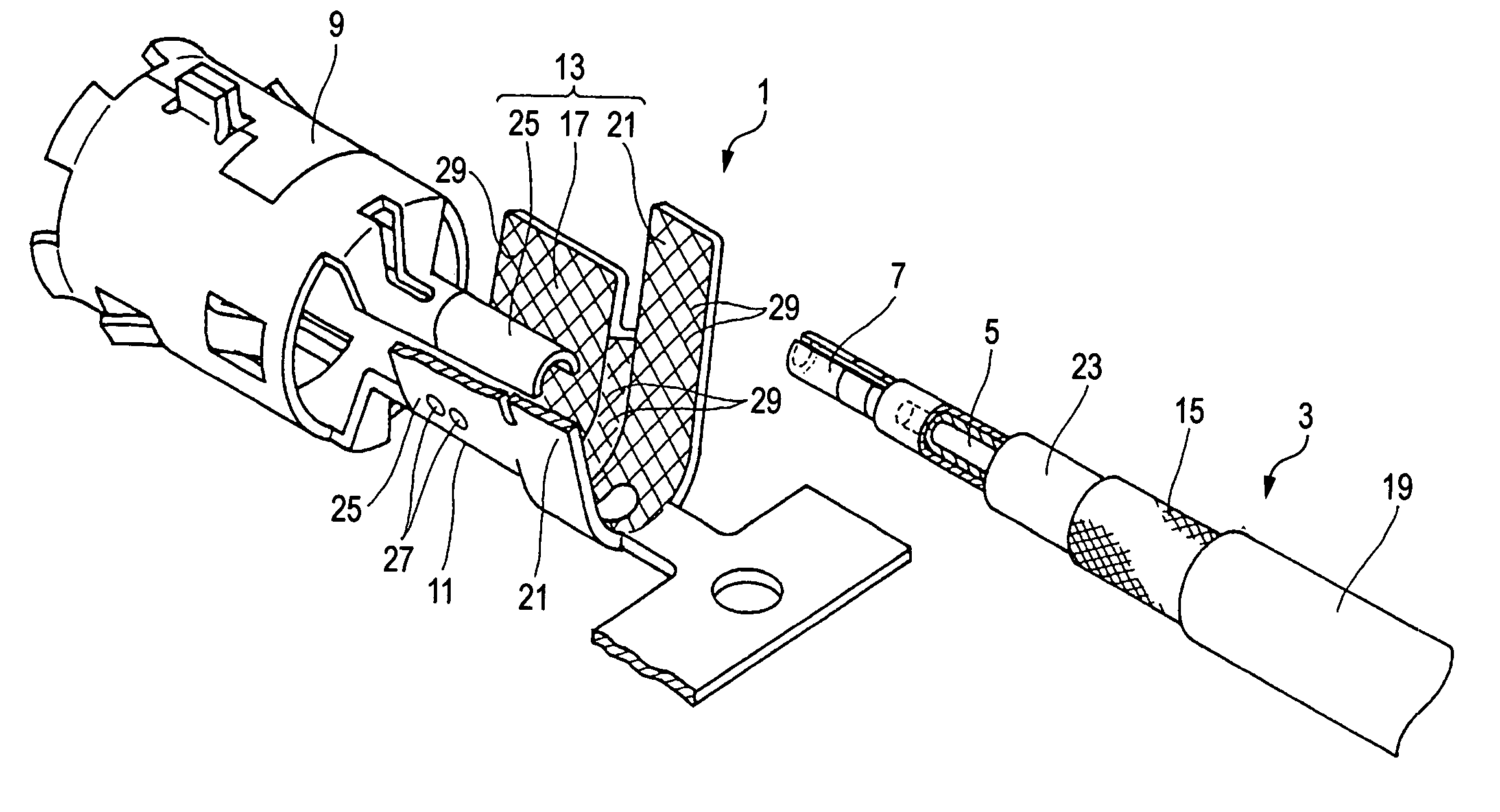
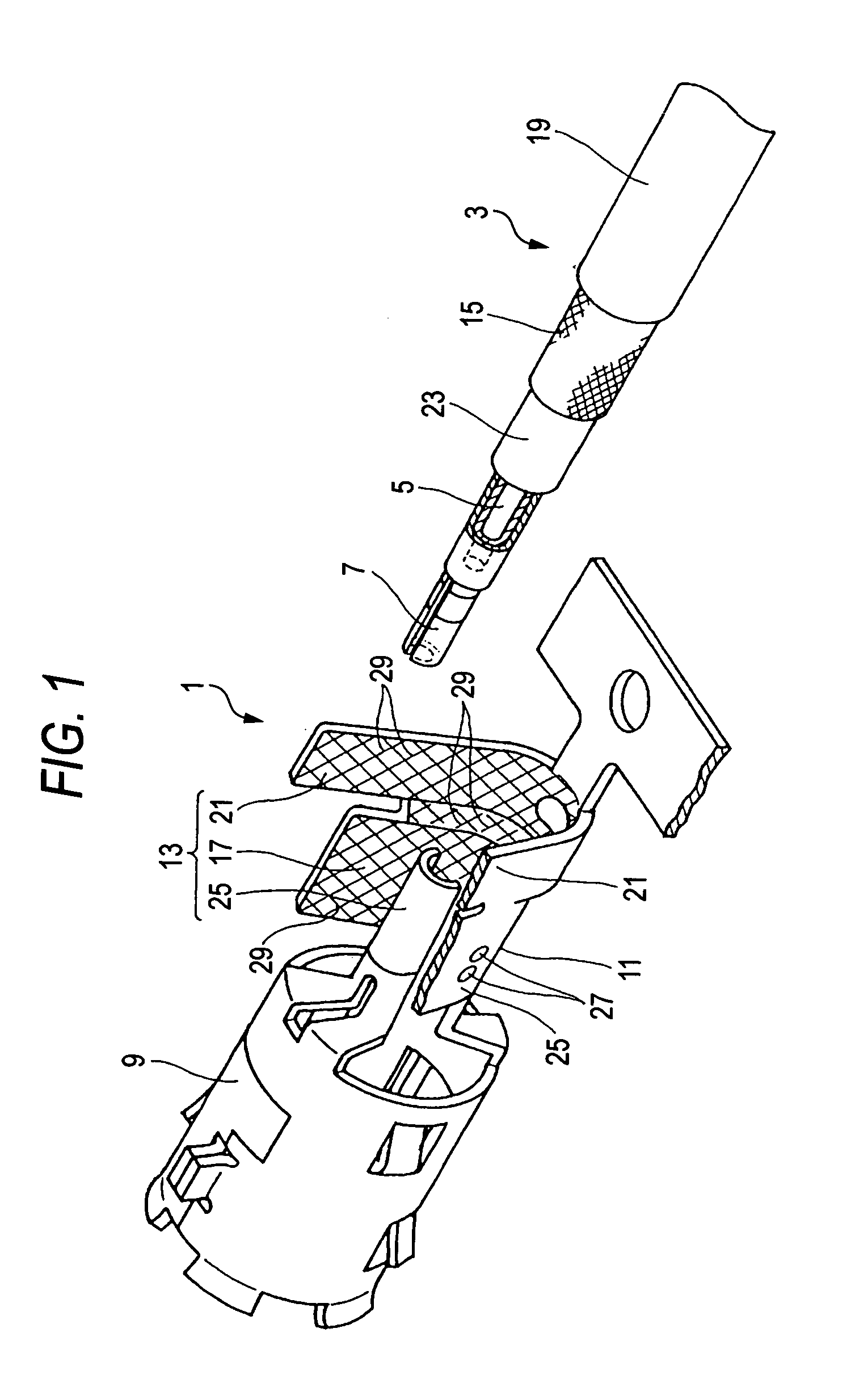
[0022] One preferred embodiment of a coaxial cable shielding terminal of the present invention will now be described with reference to FIGS. 1 to 6.

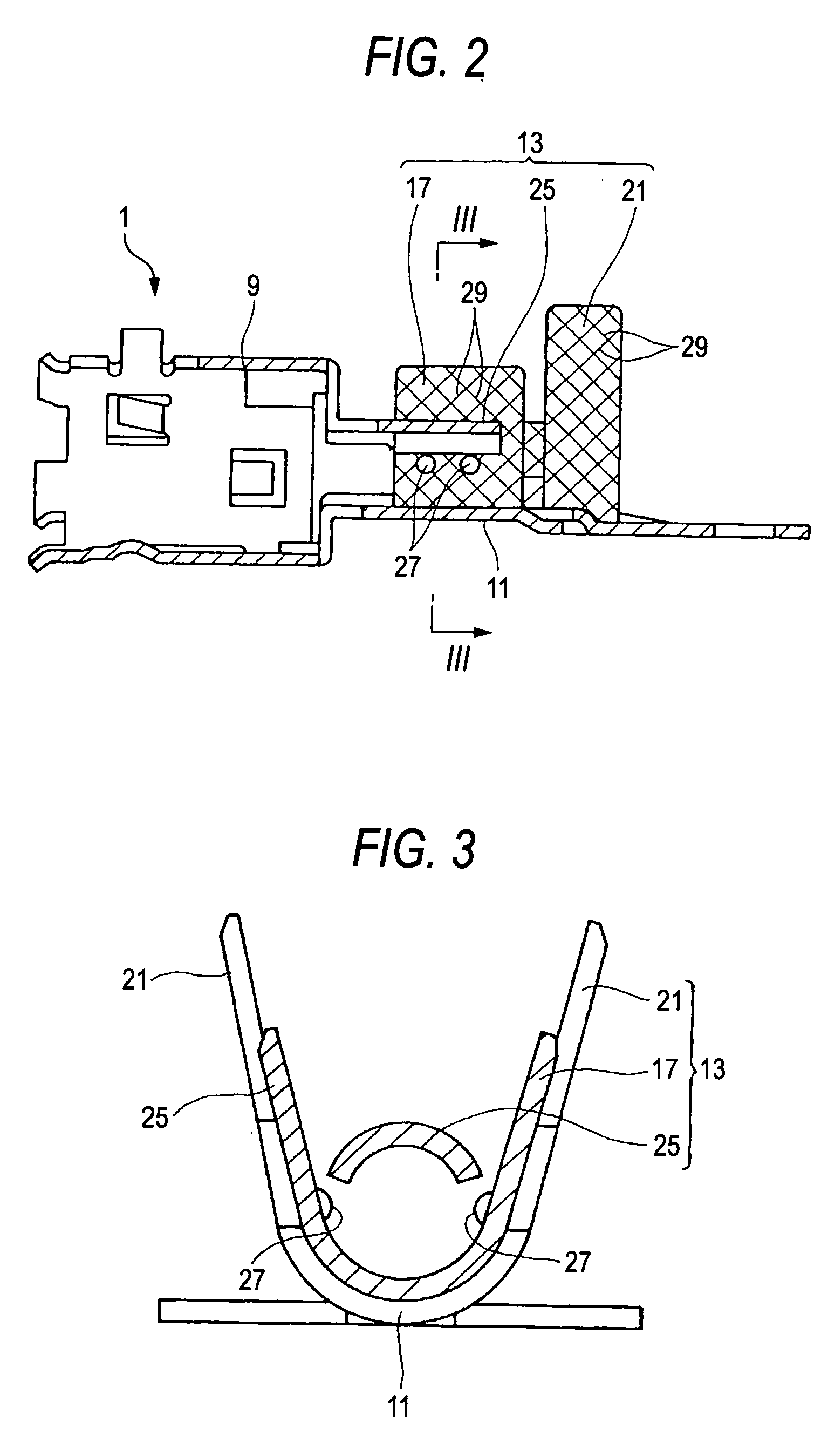
[0023] As shown in FIGS. 1 and 2, the coaxial cable shielding terminal 1 of this embodiment is an integrally-formed product formed by pressing a metal sheet, and this shielding terminal includes a terminal body 9 of a cylindrical tubular shape for receiving an inner terminal 7 (which is press-connected to a conductor 5 of the coaxial cable 3) in coaxial relation thereto, a terminal bottom plate portion 11 extending rearwardly from the terminal body 9 along the axis thereof, and the press-clamping portion 13 formed on opposite side edges of the terminal bottom plate portion 11. This shielding terminal is formed into an integral construction, using a metal sheet.

[0024] The press-clamping portion 13 includes a pair of braid press-fastening portions 17 which extend in an upstanding manner respectively from the opposite side edges of the te...


PUM


Abstract

A press-clamping portion 13 includes a pair of braid press-fastening portions 17 which extend in an upstanding manner respectively from opposite side edges of a terminal bottom plate portion 11, and can be press-connected to a braid 15 of a coaxial cable 3 by press-fastening, and a connecting piece portion 25 which can be inserted at its distal end portion between an inner insulating layer 23 of the coaxial cable 3 and the braid 15 from the end side of the coaxial cable 3 so that the braid 15 can be held between the connecting piece portion 25 and distal end portions of the braid press-fastening portions 17. Grooves 29 of a triangular cross-section are formed in an inner surface of the press-clamping portion 13, and extend in respective directions intersecting a direction of insertion of the coaxial cable 3. Each of the grooves 29 is formed such that that corner of the triangle, defining a bottom of the groove 29, is located upstream of a center of an opening of the groove 29 in the direction of insertion of the coaxial cable 3.

Description

BACKGROUND OF THE INVENTION [0001] 1. Field of the Invention [0002] This invention relates to a shielding terminal for a coaxial cable, and more particularly to a coaxial cable shielding terminal for being press-connected to an end portion of the coaxial cable. [0003] 2. Related Art [0004] Generally, in order to intercept electrical noises such as electromagnetic waves and static electricity, a coaxial cable, used as an antenna wire or the like, has a construction in which a conductor, covered with an inner insulating layer, is covered with a braid, and further this braid is covered with an insulating sheath. There have been proposed various coaxial connectors for connecting such a coaxial cable to a mating equipment or a mating connector. In such coaxial connectors, there has been used a coaxial cable shielding terminal for connecting the braid of the coaxial cable to the mating connector for grounding purposes. [0005] A conventional coaxial cable shielding terminal is formed by pr...

Claims


Application Information

Patent Timeline
Patent Type & Authority Applications(United States)
IPC IPC(8): H01R4/18H01R4/24H01R9/05H01R11/11H01R13/648H01R103/00
CPCH01R9/0518H01R4/185
Inventor YAMAGUCHI, TORUMORIKAWA, TAISHINAKAMURA, CHITOSHI
Owner YAZAKI CORP
Why Eureka
Try Eureka