Embolus blood clot filter

a filter and embolus technology, applied in the field of filters, can solve the problems of serious risks of injury to the blood vessel or inability to remove these filters, the filter is difficult to centrally position and maintain the axial alignment of the filter with the blood vessel, and the filter is difficult to remove. , to achieve the effect of convenient retrieval

Inactive Publication Date: 2005-12-01
VASCULAR INTERVENTIONAL TECH
View PDF6 Cites 75 Cited by
  • Summary
  • Abstract
  • Description
  • Claims
  • Application Information

AI Technical Summary

Benefits of technology

[0009] It is therefore an aim of the present invention to provide a new blood clot filter having self-centering feature while

Problems solved by technology

One drawback associated with permanent filters resides in the fact that permanent filters can become clogged and cause obstruction of the inferior vena cava, thereby resulting in chronic swelling of the lower extremities.
However, in practice, particularly where a filter of this type is engaged on a relatively long portion of the length thereof with the inner wall of a blood vessel, such as in the case of the filter disclosed in U.S. Pat. No. 6,059,825 issued on May 9, 2002 to Hobbs et al., it has been found that such “retrievable” filters often become securely embedded in the wall of the blood vessel as their wall engaging portions become endothelialized by the vessel wall, whereby any subsequent attempt to percutaneously remove the filters results in serious risks of injury

Method used


Image

  • Embolus blood clot filter
  • Embolus blood clot filter
  • Embolus blood clot filter

Examples


Embodiment Construction

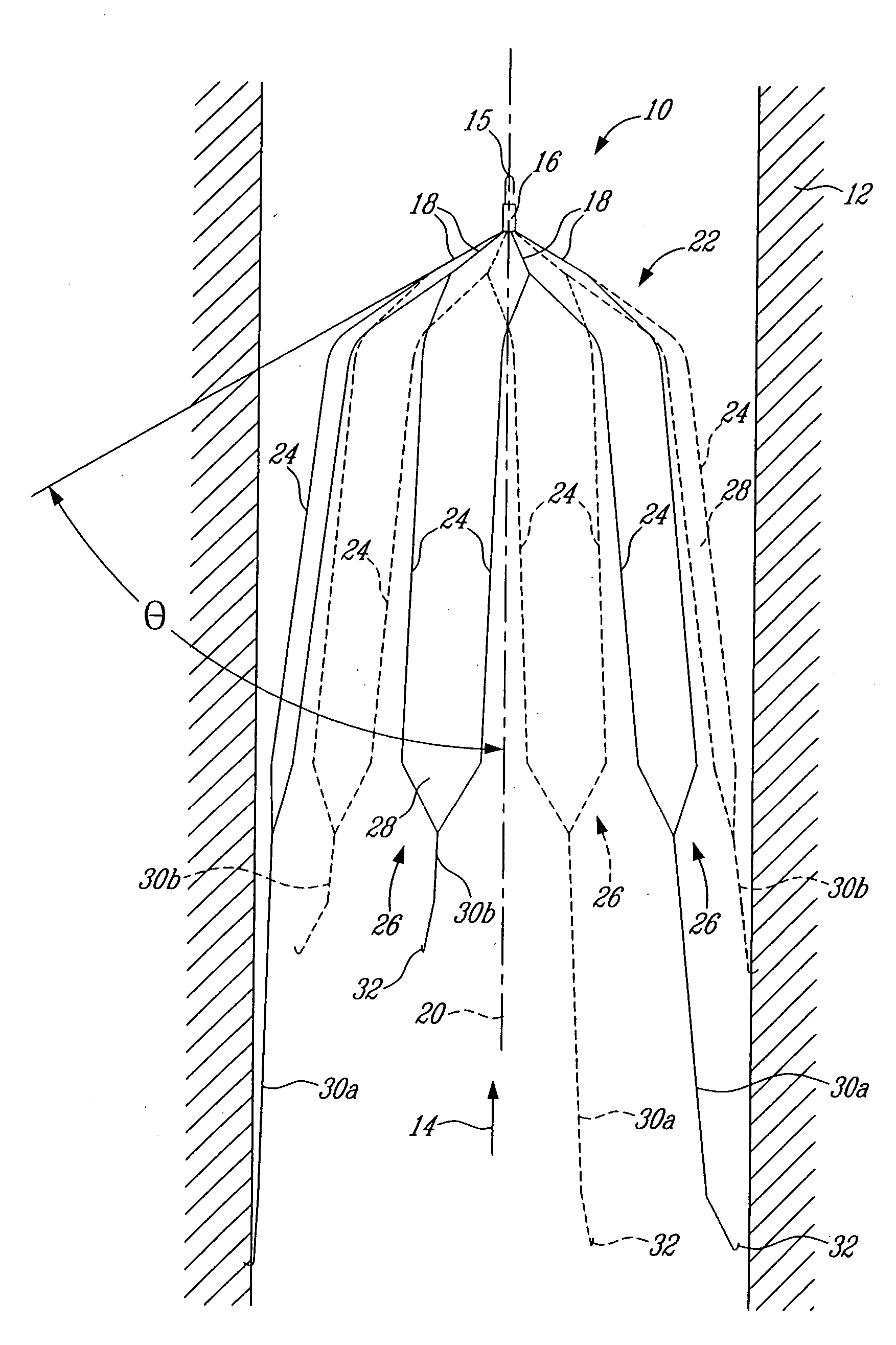
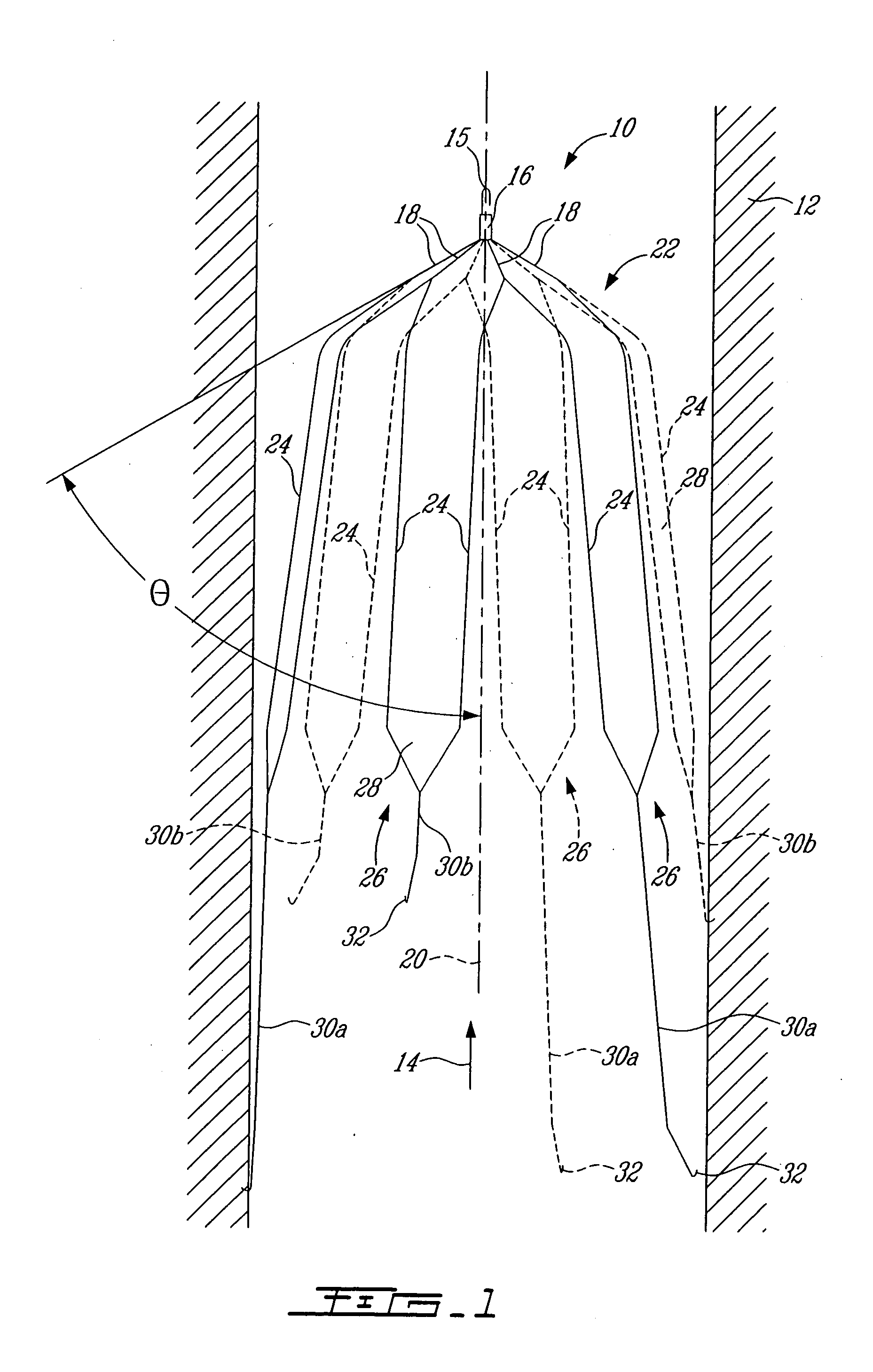
[0021] Referring now to FIG. 1, a self-centering, self-expandable blood clot filter 10 is shown anchored at two longitudinally spaced-apart locations in a blood vessel 12 (e.g. the inferior vena cava) for filtering blood clots from a stream of blood flowing in the direction indicated by arrow 14. The filter 10 is preferably placed in the vessel 12 via a delivery catheter (e.g. a 6 French Catheter) inserted through a puncture in the vessel 12. When in the catheter, the filter 10 is in a radially contracted state. Upon release from the distal end of the catheter, the filter 10 radially expands to its deployed state for securely engaging the inner wall of the vessel 12, thereby ensuring centering of the filter 10 in the vessel 12, as shown in FIG. 1. The filter 10 is preferably made out of a shape memory material or a temperature responsive material. According to a preferred embodiment of the present invention, the filter 10 is formed of Nitinol, an alloy of titanium and nickel. In thi...


PUM


Abstract

A blood clot filter (10) comprises a number of diverging legs (26) extending from a common central hub (16) to define a blood clot reservoir. Adjacent legs (26) share a common root (18) from which branches off at least two main branches (24). Each main branch (24) connects at a distal end to an adjacent main branch (24) to form a plurality of interconnected anchoring members (30a, 30b) about an open upstream end of the blood clot reservoir.

Description

RELATED APPLICATIONS [0001] This is a continuation of International Patent Application No. PCT / CA2003 / 001864 filed Nov. 28, 2003, which claims benefit of U.S. Provisional Patent Application No. 60 / 429,545 filed on Nov. 29, 2002. The contents of both of which are herein incorporated by reference.BACKGROUND OF THE INVENTION [0002] 1. Field of the Invention [0003] The present invention relates to filters and, more particularly, to a blood clot filter which is particularly suited for filtering emboli from blood circulating through a blood vessel. [0004] 2. Description of the Prior Art [0005] It is well known to introduce a filter in the inferior vena cava of a patient to prevent pulmonary embolism. Most presently available blood clot filters are permanently implanted in the inferior vena cava and remain there for the duration of the patient's life. One drawback associated with permanent filters resides in the fact that permanent filters can become clogged and cause obstruction of the in...

Claims


Application Information

Patent Timeline
IPC IPC(8): A61F2/01A61M29/00
CPCA61F2/01A61F2230/008A61F2230/005A61F2002/016A61F2/0105
Inventor OLIVA, VINCENTSOULEZ, GILLES
Owner VASCULAR INTERVENTIONAL TECH
Why Eureka
Try Eureka