Electronic sight for firearm, and method of operating same

a technology of electronic sight and firearm, applied in the field of electronic sight, can solve the problems of not being satisfactory in all respects, affecting the trajectory of a bullet, cumbersome and slow,

Inactive Publication Date: 2005-12-08
RAYTHEON CO
View PDF63 Cites 222 Cited by
  • Summary
  • Abstract
  • Description
  • Claims
  • Application Information

AI Technical Summary

Benefits of technology

[0009] From the foregoing it may be appreciated that a need has arisen for a firearm sight which avoids some or all of the disadvantages that are associated with pre-existing sights.

Problems solved by technology

Although existing firearm sights have been generally adequate for their intended purposes, they have not been satisfactory in all respects.
However, during subsequent use of the firearm and sight, for example when hunting, a variety of conditions can vary from the conditions that existed during the alignment or zeroing process, and can thus affect the trajectory of a bullet.
But this approach is complex, cumbersome and slow, and thus impractical for most real-world situations.
Moreover, even this approach usually involves a significant degree of mental guesswork as to what the current conditions are.
Given the variety of different factors that can influence the trajectory of a bullet, attempts of this type to mentally and visually effect compensation involve a significant degree of estimation and guesswork, and frequently result in the bullet missing the target altogether, or hitting the target at a location which is spaced from the desired impact point.
A further problem is that, at any given point in time, existing sights use a selected reticle which has various predetermined characteristics, such as color, shape, size and / or brightness.
Thus, for example, if the reticle is a dark color and the target also happens to be a dark color, it may be very difficult to distinguish the reticle from the target when the reticle is aligned with the target.
Still another consideration is that, when looking through an existing sight, it is sometimes difficult to identify and / or distinguish a potential target from other portions of the scene being viewed through the sight.

Method used


Image

  • Electronic sight for firearm, and method of operating same
  • Electronic sight for firearm, and method of operating same
  • Electronic sight for firearm, and method of operating same

Examples


Embodiment Construction

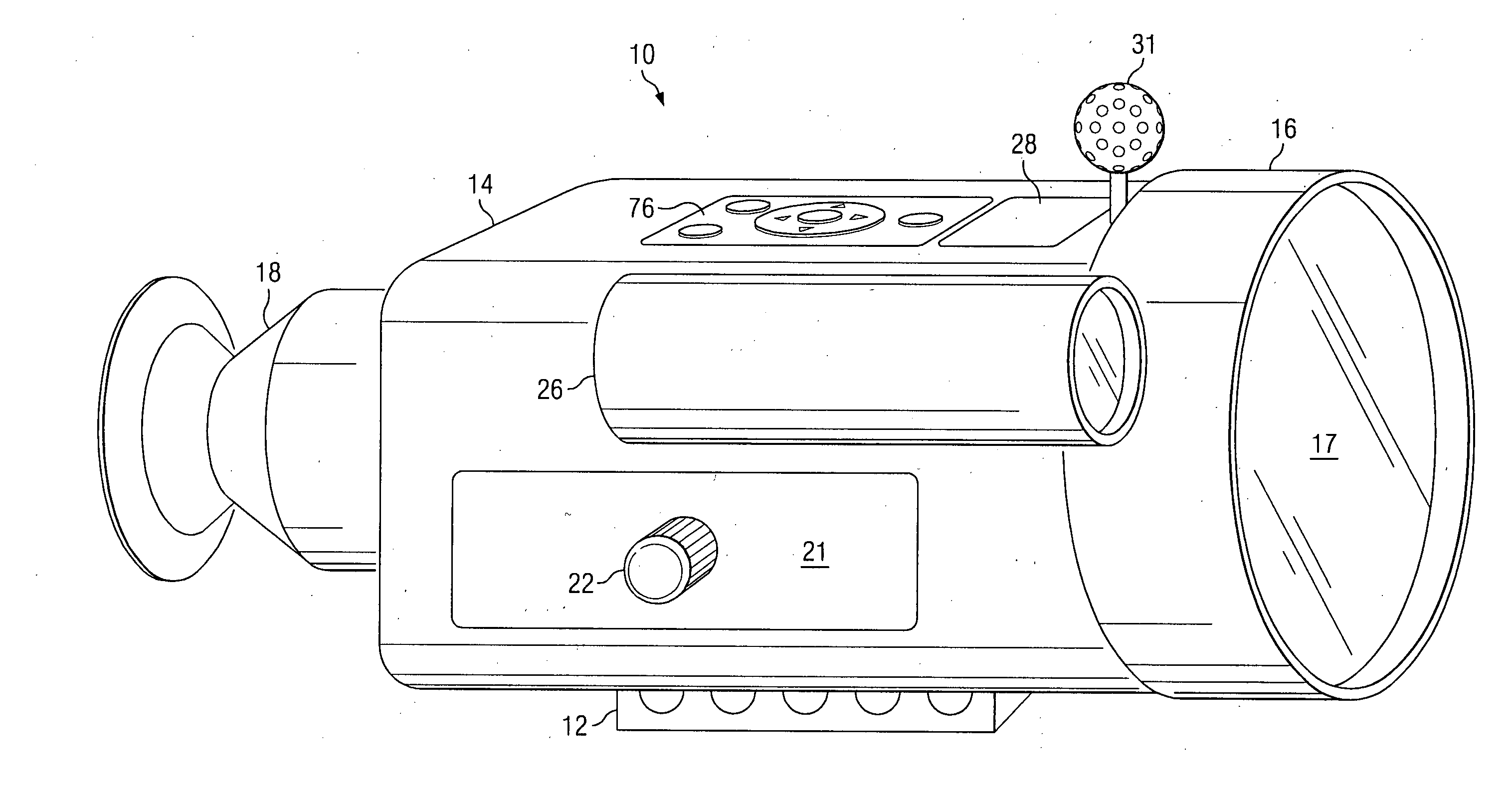
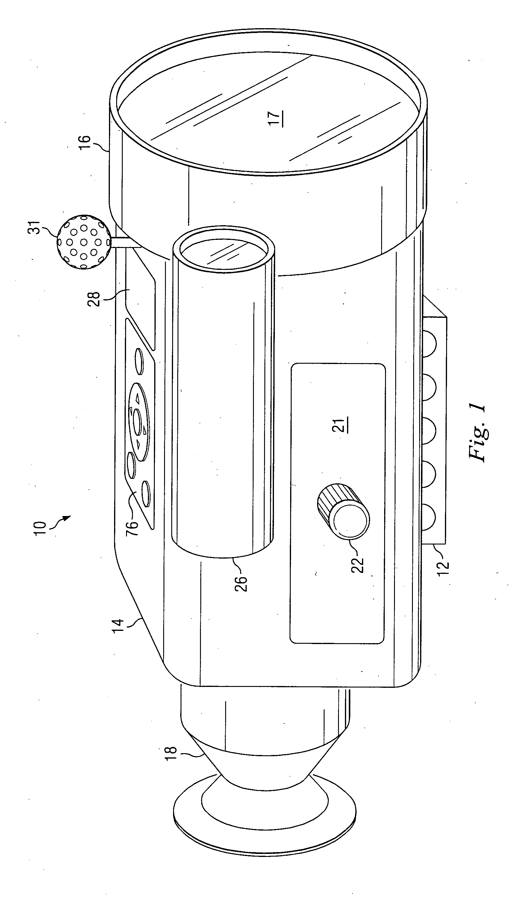
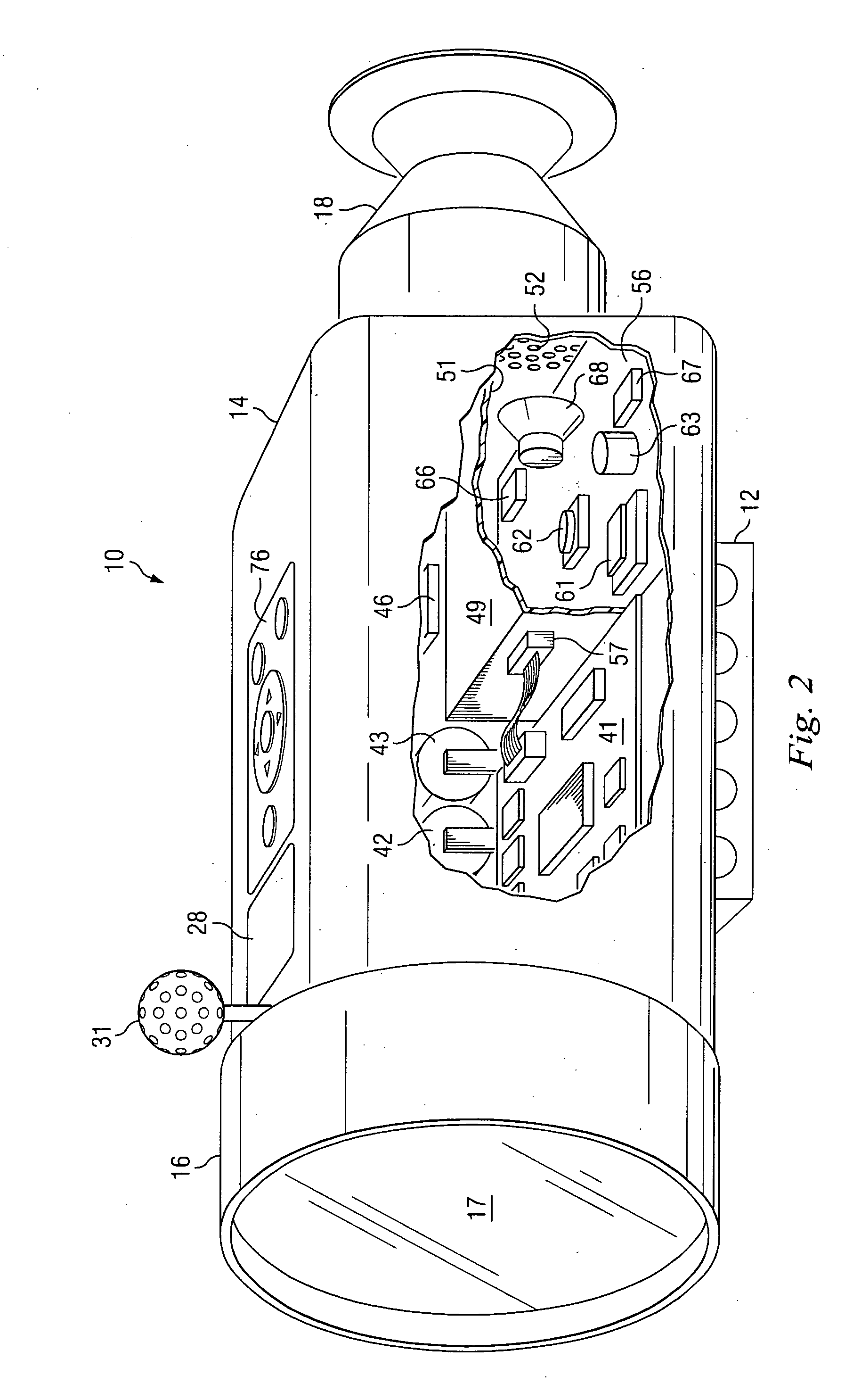
[0032]FIG. 1 is a diagrammatic perspective view of an apparatus which is a digital rifle sight 10, and which embodies aspects of the present invention. Although the sight 10 is referred to herein as a “rifle sight”, it can actually be used not only with rifles, but also with other types of firearms, such as target pistols. The sight 10 includes a rail mount 12, which can fixedly and securely mount the sight 10 on the receiver or mounting rail of a firearm.

[0033] The sight 10 includes a housing 14, which has at a front end thereof an objective lens section 16 that includes at least one lens 17, and which has at a rear end thereof an eyepiece optics section 18. The housing 14 has an access panel 21, which is removably held in place by a thumbscrew 22. The access panel 21 can be removed in order to provide access to an internal compartment that contains selected components, as discussed in more detail later.

[0034] The sight 10 has a laser rangefinder 26, which is fixedly mounted on o...


PUM


Abstract

A firearm sight receives information regarding a factor, and then automatically adjusts the relative positions of a digital reticle and an image on a viewing section to compensate for the influence of the factor on a projectile trajectory. A different feature involves automatically adjusting a characteristic of the reticle based on the image. Another feature involves automatically adjusting the digital image to distinguish a portion thereof aligned with the reticle from an adjacent portion thereof. Yet another feature involves causing the firearm sight to generate an audible sound. Still another feature involves presenting information on the viewing section which represents the position of the firearm sight on the surface of the earth.

Description

TECHNICAL FIELD OF THE INVENTION [0001] This invention relates in general to a device which facilitates accurate aiming of a firearm and, more particularly, to a firearm sight which is mounted on the firearm, and through which a user observes a potential target. BACKGROUND OF THE INVENTION [0002] Over the years, various techniques and devices have been developed to help a person accurately aim a firearm, such as a rifle or target pistol. One common approach is to mount on the firearm's barrel a sight or scope, through which the person views the intended target in association with a reticle, often with a degree of magnification. Although existing firearm sights have been generally adequate for their intended purposes, they have not been satisfactory in all respects. [0003] For example, when a sight is first mounted on the barrel of a firearm, it needs to be aligned or “zeroed” with the firearm barrel, typically through a trial and error process. For example, a person may shoot one or...

Claims


Application Information

Patent Timeline
Patent Type & Authority Applications(United States)
IPC IPC(8): F41G1/00F41G1/38F41G1/473
CPCF41G1/38F41G3/08F41G3/06
Inventor COX, PHILLIP A.FLORENCE, JAMES M.
Owner RAYTHEON CO
Why Eureka
Try Eureka