Hydraulic cylinder

a technology of hydraulic cylinder and piston, which is applied in the direction of hydraulic actuation system, rotary clutch, fluid coupling, etc., can solve the problems of inability to detect the position of the piston, undetected idle path and dead time in the hydraulic actuation system, and insufficient ventilation of the pressure space when installed horizontally, so as to increase the effective cross section of the after-running means, increase the flow rate, and reduce the effect of idle path

a technology of hydraulic cylinder and piston, which is applied in the direction of hydraulic actuation system, rotary clutch, fluid coupling, etc., can solve the problems of inability to detect the position of the piston, undetected idle path and dead time in the hydraulic actuation system, and insufficient ventilation of the pressure space when installed horizontally, so as to increase the effective cross section of the after-running means, increase the flow rate, and reduce the effect of idle path

US20050268608A1Inactive Publication Date: 2005-12-08ZF FRIEDRICHSHAFEN AG

Image

  • Hydraulic cylinder
  • Hydraulic cylinder
  • Hydraulic cylinder

Examples


Embodiment Construction

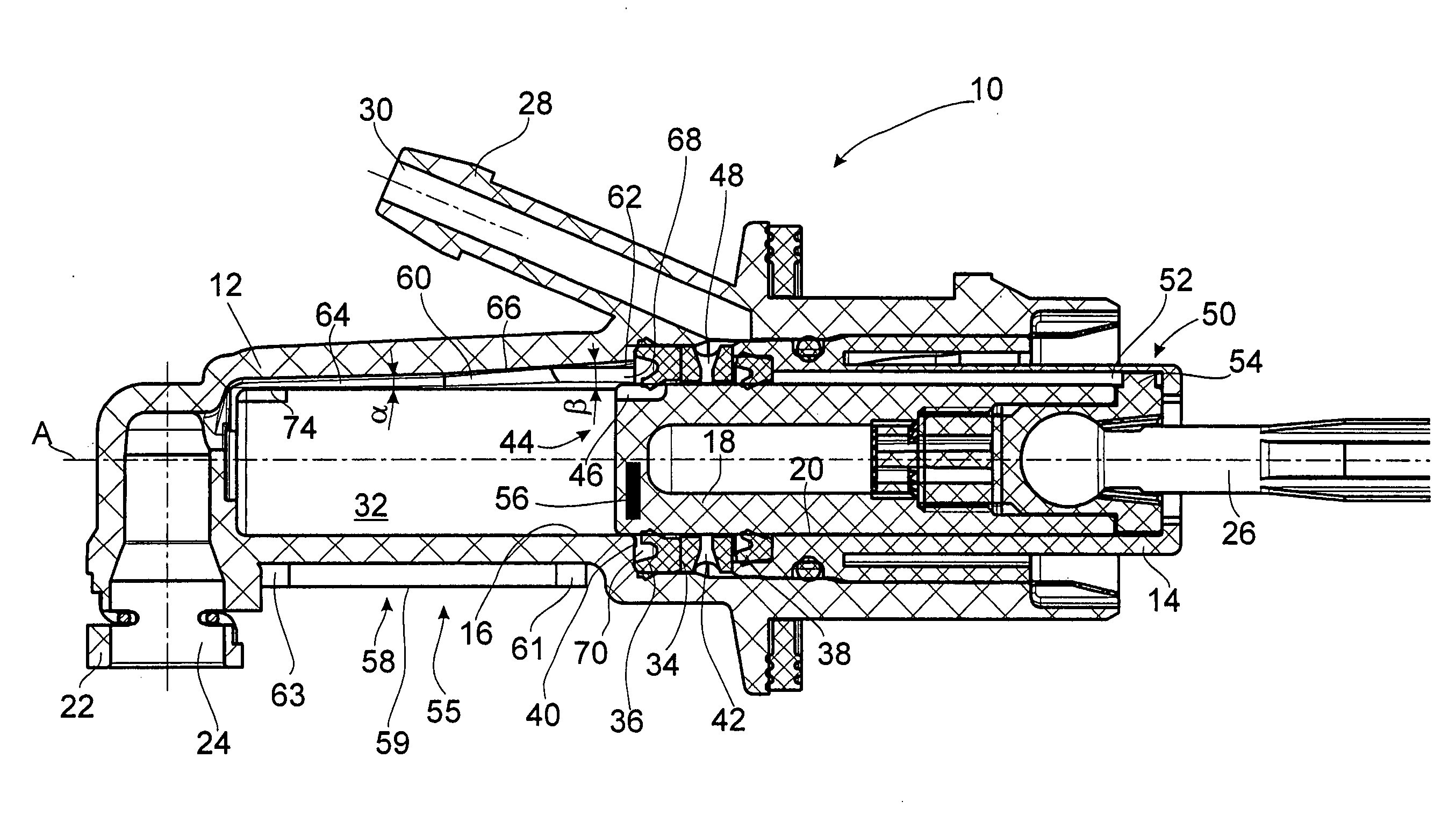
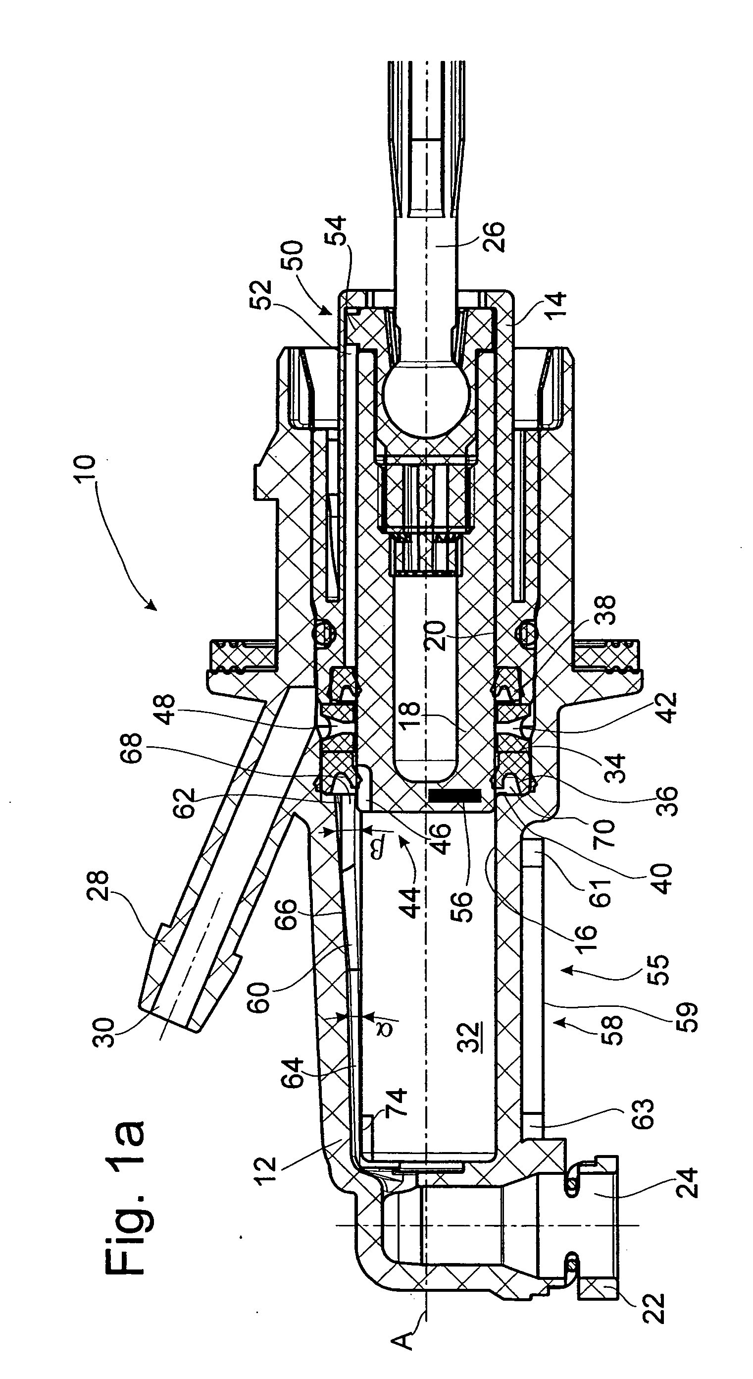
[0034]FIG. 1a shows a view in axial section of a hydraulic cylinder 10, according to the invention, which has an after-running device and is constructed as a master cylinder for a hydraulic actuator for actuating a motor vehicle clutch. The master cylinder 10 has a plastic housing 12 and a guide pipe 14 which is arranged in a stepped bore hole and fixedly connected to the housing 12, which jointly form a running sleeve 16 for a plastic piston 18 with a running surface 20 axially movable in the cylinder 10.

[0035] At its end, the housing 12 comprises a fluid connection 22 having a fluid channel 24 and communicating with respect to flow with a slave cylinder, not shown. The piston 18 of the master cylinder 10 is in operative connection with a clutch pedal, not shown, by means of a piston rod 26 that is swivelably arranged at the piston 18. When the clutch pedal is actuated, the piston rod 26 is displaced toward the left with reference to the drawing and, via the fluid connection, cont...


PUM


Abstract

A hydraulic cylinder includes a housing having a fluid connection for connecting to a hydraulic system and an after-running connection for connecting to a fluid after-running vessel, and a piston which is axially displaceable in the housing to define a variable pressure space having a gas collecting portion, the piston being fixed against rotation in the housing and having at least one after-running groove which is oriented substantially toward the gas collecting portion. A primary seal arranged in the housing and receiving the piston therethrough is bridged by the after-running groove when the piston is in an extended end position, whereby the gas collecting portion of the pressure space communicates with the after-running connection when the piston is in the extended end position.

Description

BACKGROUND OF THE INVENTION [0001] 1. Field of the Invention [0002] The invention is directed to a hydraulic cylinder including a housing having a fluid connection for connecting to a hydraulic system and an after-running connection for connecting to a fluid after running vessel, a piston which is axially displaceable in the housing to define a variable pressure space, a seal isolating the pressure space from the atmosphere, and an after-running groove which bridges the seal when the piston is in an extended end position. [0003] 2. Description of the Related Art [0004] A hydraulic cylinder of the type mentioned above, such as is applied, for example, in automotive engineering in hydraulic clutch systems or brake actuation systems, is known, e.g., from U.S. Pat. No. 6,584,771. [0005] The housing of the hydraulic cylinder shown in the above-cited publication has, at its end side, a connection for a pressure line and, at its jacket surface, a connection with an after-running channel ex...

Claims


Application Information

Patent Timeline
08 Dec 2005
Publication
US20050268608A1
IPC
F02D1/00; F16D25/08
CPC
F16D2500/3026; F16D25/088; F16D25/08; F16D2025/081
Inventors
LUDSTECK, SVEN; GEBAUER, DIETER