Premixing burner with impingement cooled centerbody and method of cooling centerbody

a technology of impingement cooling and premixing burner, which is applied in the direction of machines/engines, lighting and heating apparatus, combustion types, etc., can solve the problems of affecting flame stability and lean blowout, affecting and limited flame stability, and conventional premixing burners as described above may suffer from dynamics sensitivity and lean stability degradation, etc., to improve flame stability and dynamic sensitivity to pressure fluctuations

Inactive Publication Date: 2005-12-08
GENERAL ELECTRIC CO
View PDF13 Cites 35 Cited by
  • Summary
  • Abstract
  • Description
  • Claims
  • Application Information

AI Technical Summary

Benefits of technology

[0011] In an embodiment of the invention, impingement cooling technology is applied to a premixing burner to cool the face of the bluff centerbody that is exposed to high-temperature flame at the aft end. Thus, the invention reduces the quantity o

Problems solved by technology

Flame stability and lean blow out are influenced and limited by the air used for cooling and purge.
Conventional premixing burners as described above may suffer from dynamics sensitivity and lean stability degradation by the discharge of fuel nozzle and centerbody cooling and p

Method used


Image

  • Premixing burner with impingement cooled centerbody and method of cooling centerbody
  • Premixing burner with impingement cooled centerbody and method of cooling centerbody
  • Premixing burner with impingement cooled centerbody and method of cooling centerbody

Examples


Embodiment Construction

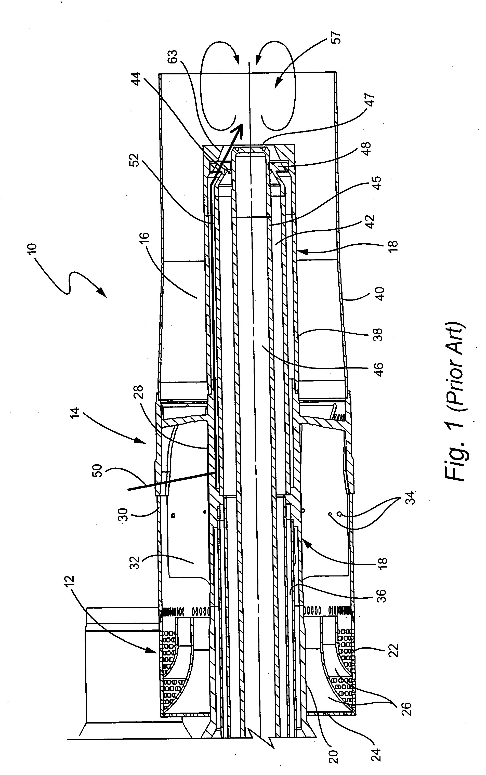
[0019] Conventional premixing burners of the type illustrated in FIG. 2 may suffer from dynamic sensitivity and lean stability degradation by the discharge of fuel nozzle and centerbody cooling and purge air directly in the recirculation zone behind the bluff body. This air both dilutes the mixture in the recirculation zone and leads to unstable combustion due to reduction of the fine temperature and unstable feedback to the pressure ratio across the discharge orifice.

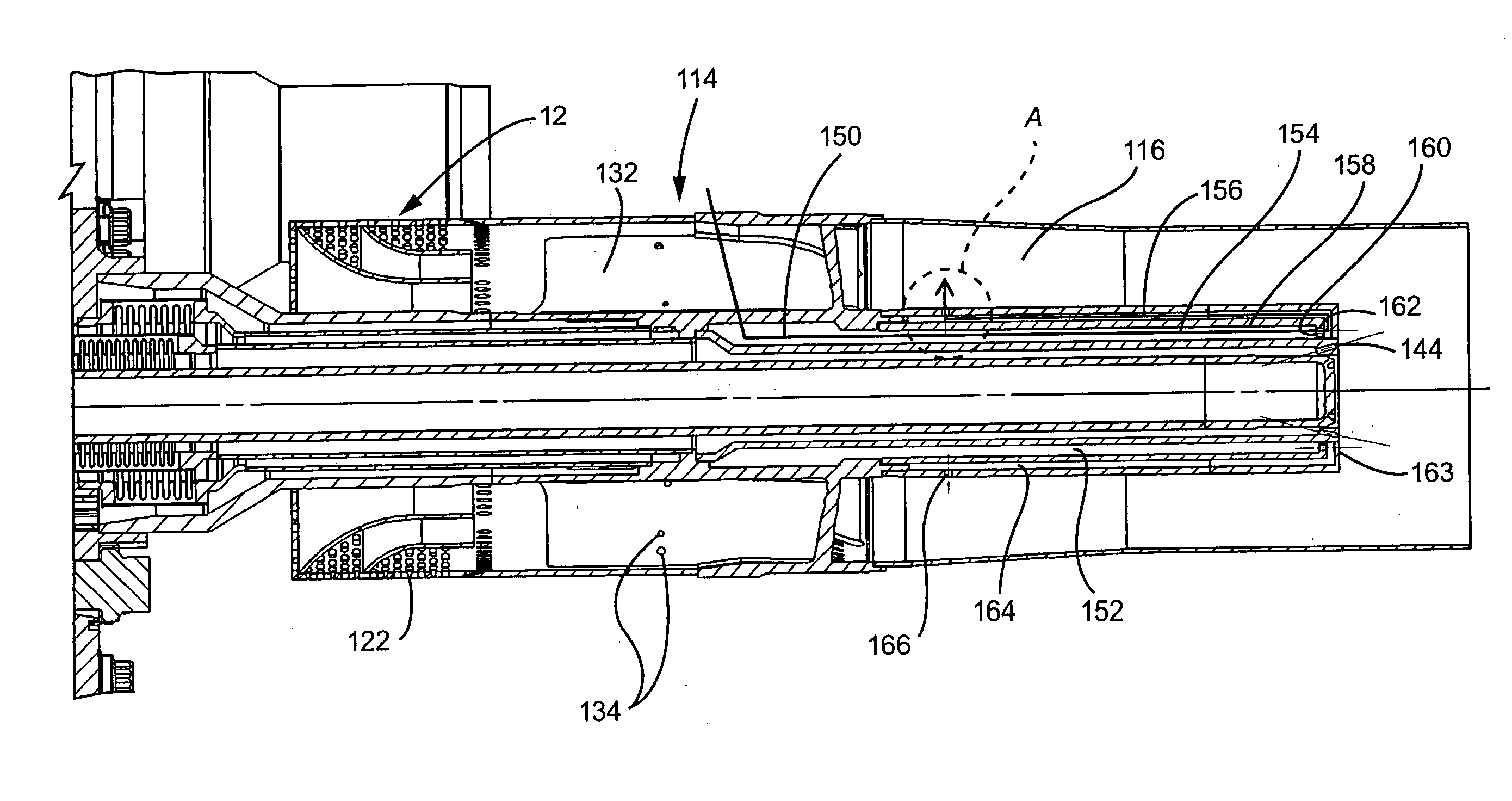
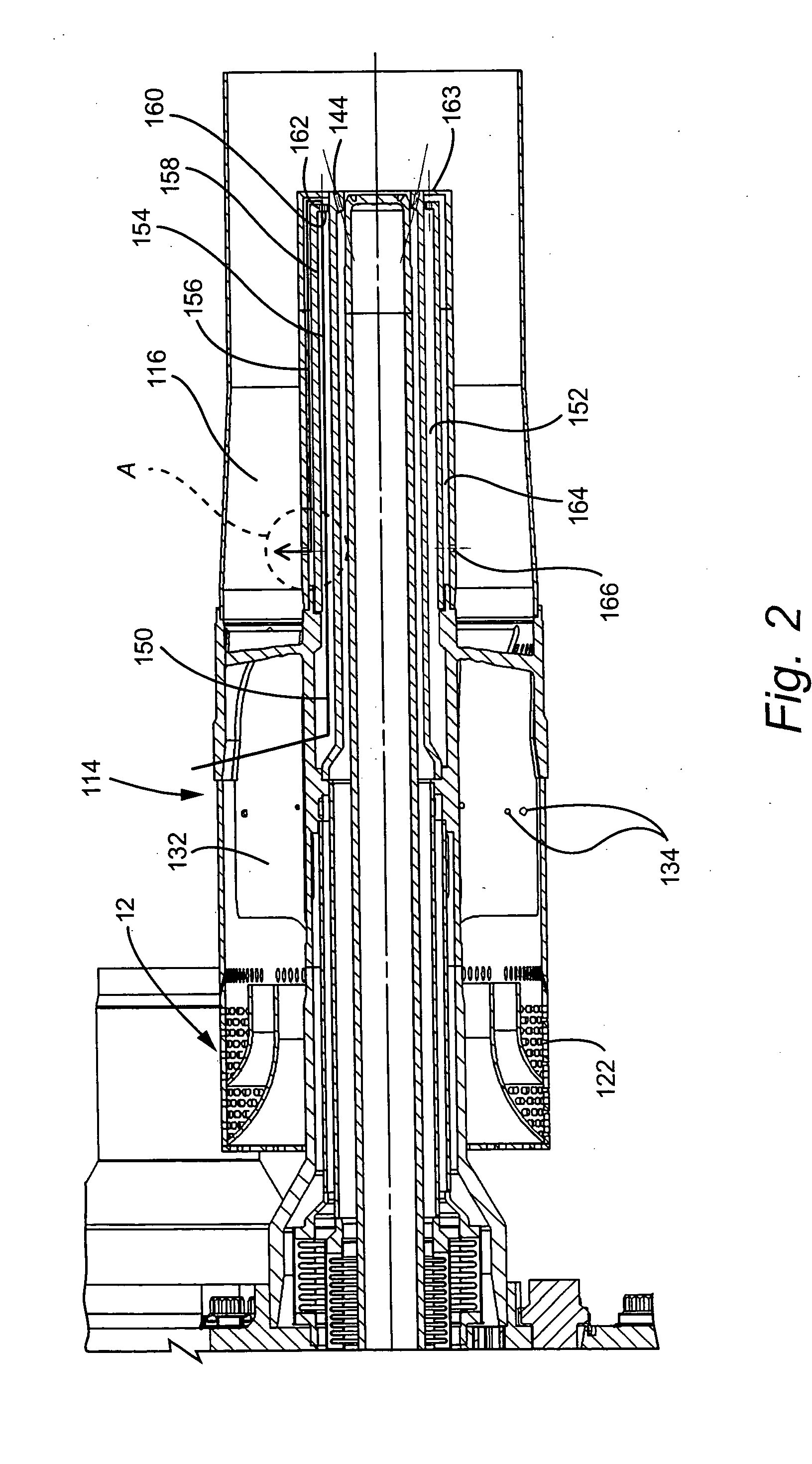
[0020] A burner assembly provided as a first embodiment of the invention is illustrated by way of example in FIGS. 2-4. For ease of explanation and understanding, components of this burner that generally correspond to components of the above-described conventional burner are designated with corresponding reference numbers, incremented by 100, but the description thereof is limited to that required to call out the differences between the inventive configuration and the conventional assembly.

[0021] In an embodiment of ...


PUM


Abstract

A gas-air premixing burner for gas turbines includes an air swirler and an annular burner tube surrounding a bluff centerbody. The bluff body serves to stabilize the flame by defining a recirculating vortex. Cooling air is directed to impinge against the bluff face of the centerbody and the spent impingement cooling air flows in a reverse direction towards the air swirler within the centerbody and is discharged through holes at the outer diameter of the centerbody, where it mixes with the fuel/air mixture prior to reaching the flame zone.

Description

BACKGROUND OF THE INVENTION [0001] The invention relates to a fuel nozzle such as a gas-air premixing burner for use in gas turbines, comprising an air swirler and annular burner tube surrounding a bluff centerbody. More particularly, the invention relates to a nozzle end configuration and to an adaptation for cooling the same. [0002] Gas turbines for power generation are generally available with fuel nozzles configured for either “Dual Fuel” or “Gas Only”. “Gas Only” refers to operation burning, for example, natural gas and “Dual Fuel” refers to having the capability of operation burning either natural gas or liquid fuel. The “Dual Fuel” configuration is generally applied with oil used as a backup fuel, if natural gas is unavailable. The “Gas Only” configuration is offered in order to reduce costs as the nozzle parts and all associated equipment required for liquid fuel operation are not supplied. In general, fuel nozzles are designed to have “Dual Fuel” capability and the “Gas Onl...

Claims


Application Information

Patent Timeline
IPC IPC(8): F02C7/22F23R3/28F02C7/232F23D14/48F23R3/14
CPCF23R3/286F23D14/78
Inventor WIDENER, STANLEY KEVIN
Owner GENERAL ELECTRIC CO
Why Eureka
Try Eureka