Container leak detection apparatus and method

a leak detection and container technology, applied in the direction of fluid leakage detection, fluid tightness measurement, instruments, etc., can solve the problems of malformed necks, contact with containers, hot and tacky freshly blow-molded containers,

Active Publication Date: 2005-12-08
GENERAL ELECTRIC CAPITAL AS AGENT
View PDF39 Cites 16 Cited by
  • Summary
  • Abstract
  • Description
  • Claims
  • Application Information

AI Technical Summary

Benefits of technology

[0007] The test components of the apparatus include a test probe that is lowered onto a container opening so that testing can occur as the container and test probe move down the conveyor. This test probe inputs air into the container and measures the resulting pressure and pressure decay over time. The test is short enough that it can take place within the several inches the probe assembly travels on the conveyor. Certain sensors, such as a photo-eye that detects when a container is present and an encoder that detects conveyor speed, enable the apparatus to test containers that are spaced apart at random intervals on the conveyor.

Problems solved by technology

Such defects may include but are not limited to pin holes, malformed necks and neck obstructions that could inhibit filling.
Freshly blow-molded containers may be hot and tacky.
Contact with the container is in this state is undesirable as it can mar the fresh surface of the container and may cause containers to tip over and or jam the conveyor.
Thus, time and product is wasted if even a single container becomes out of line.
Greisbeck, however, requires that the containers be stabilized upon a carousel platform for testing which makes container handling more demanding and expensive.
Further, the device cannot be easily used with an existing conveyor.

Method used


Image

  • Container leak detection apparatus and method
  • Container leak detection apparatus and method
  • Container leak detection apparatus and method

Examples


Embodiment Construction

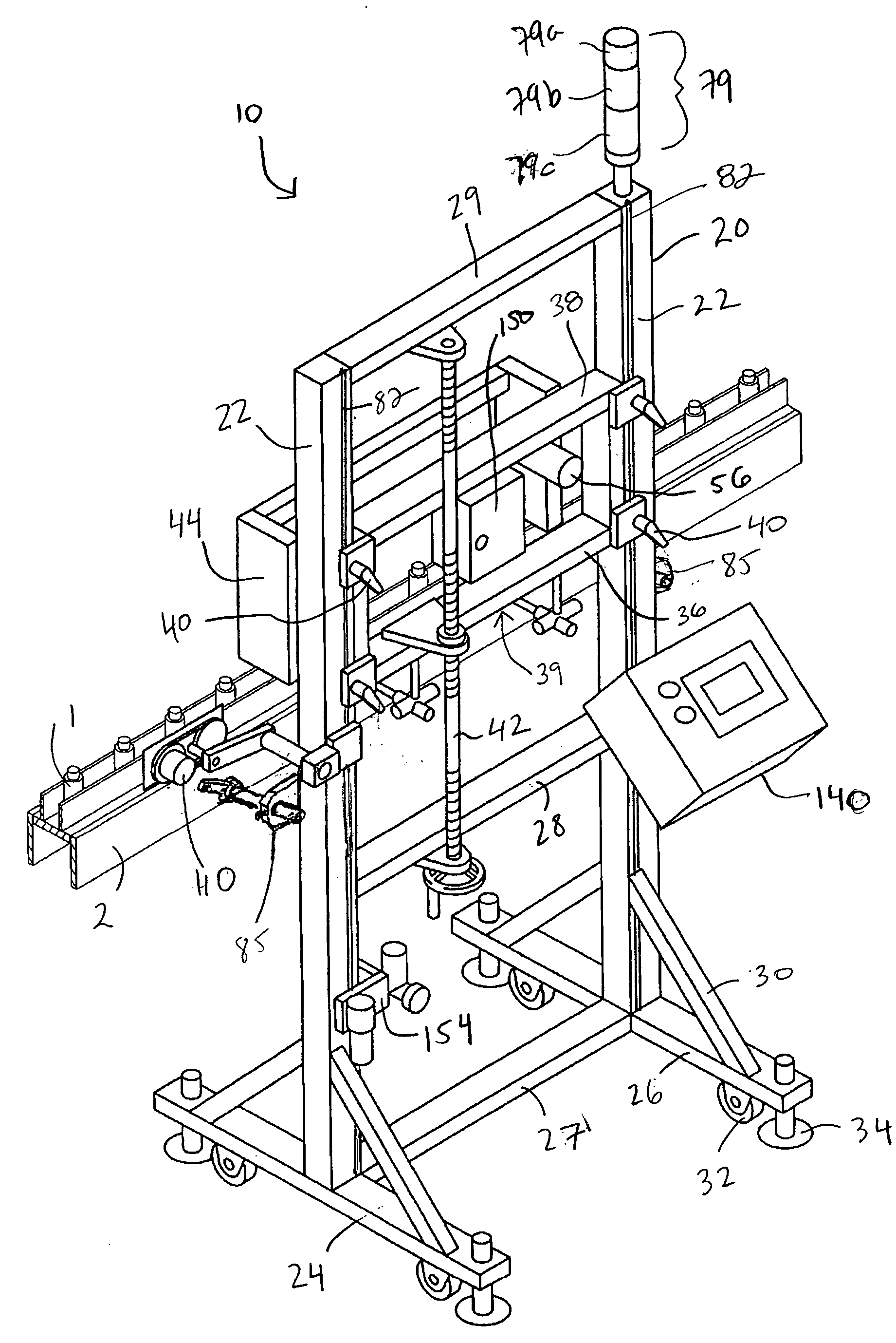
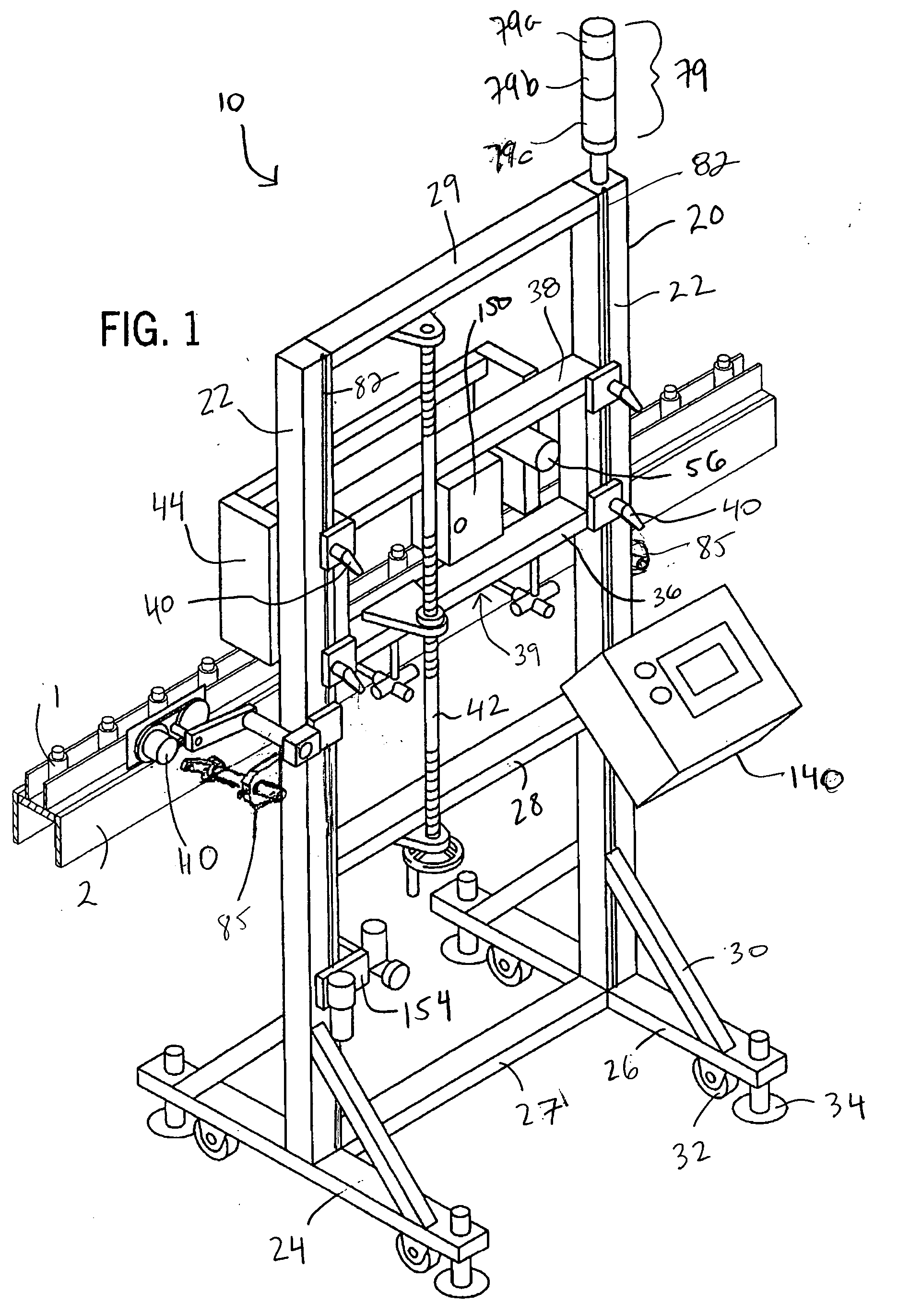
[0027] In reference to FIG. 1, the apparatus 10 of the present invention is utilized for testing a recently molded plastic bottle 1. It is possible to test containers or “closed volumes” of different sizes and shapes. It is also possible to test containers made from different kinds of materials, i.e. the invention is not limited to testing plastic containers.

[0028] The apparatus 10 of the present invention is portable, and can be adapted to fit various conveyors 2. In the figures of the present description, only a portion of a conveyor 2 is shown. The full conveyor 2 may have various configurations, which configurations can be accommodated by the adjustable frame 20 on which are mounted various components of the apparatus.

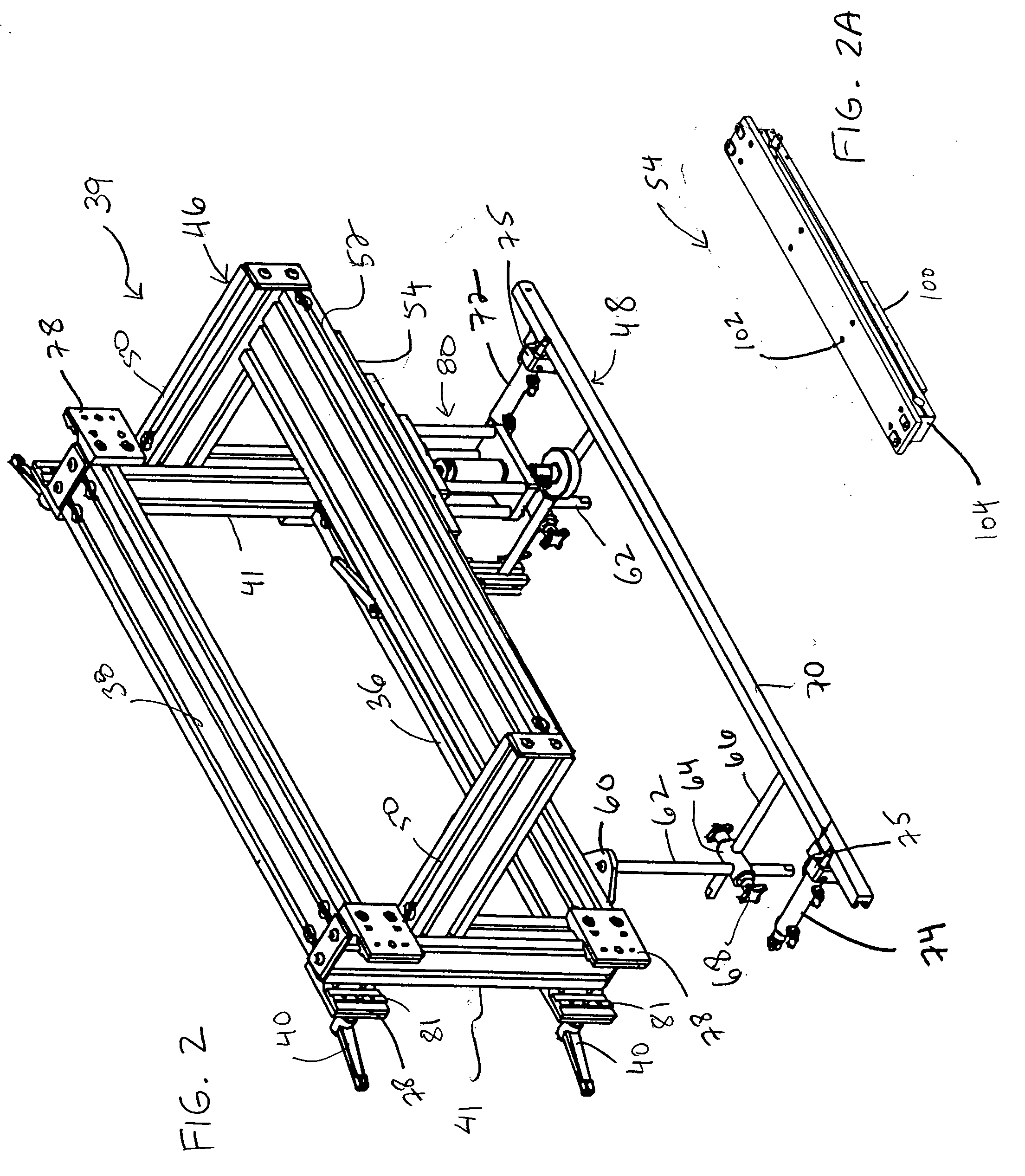
[0029] The apparatus 10 components include a probe assembly 80 that further includes a test head assembly 90 (see FIG. 4). In general, the probe assembly 80 moves reciprocatingly from a predetermined starting point to synchronize sequentially with each container ...


PUM

PropertyMeasurementUnit
speedaaaaaaaaaa
pressureaaaaaaaaaa
pneumatic pressureaaaaaaaaaa

Abstract

An apparatus and method for testing a container as to leakage and defects. The apparatus is especially useful for testing plastic bottles because it does not contact one or more of the bottle sides during testing. A frame with the test components may be adjusted so that the apparatus will fit many different conveyor configurations and container sizes. A container is moved along by a conveyor, where it is sensed by a photo-eye to initiate testing. The test probe makes contact with the container opening, and travels with the container during testing. The test probe introduces air into the container and detects the maximum pressure and pressure decay. If the pressures are not within an acceptable range, the container is ejected from the conveyor.

Description

BACKGROUND OF THE INVENTION [0001] The present invention relates generally to a leak and defect testing device for containers, and more particularly to a continuously operating device that tests for leaks and defects in containers. [0002] When containers are manufactured, especially blow-molded plastic containers, it is of great importance to be able to test the containers for leaks and defects before they are put into use. Such defects may include but are not limited to pin holes, malformed necks and neck obstructions that could inhibit filling. [0003] A number of devices for testing container defects are known. As containers are conveyed along or through one of these prior devices, they may be “handled” using various methods, e.g. by using holding tools that maintain each container in a stationary position during testing, or by continuously stopping the conveyor so that each container may be tested. Freshly blow-molded containers may be hot and tacky. Contact with the container is...

Claims


Application Information

Patent Timeline
Patent Type & Authority Applications(United States)
IPC IPC(8): B07C5/34B65G43/00B65G47/00G01M3/04G01M3/36G01N1/00
CPCG01M3/366B07C5/3404
Inventor STRAND, EDWARD JAMESDAWLEY, JAMES MICHAEL
Owner GENERAL ELECTRIC CAPITAL AS AGENT
Why Eureka
Try Eureka