Electro-hydraulic actuation system

a technology of electrohydraulic actuators and hydraulic actuators, applied in fluid couplings, clutches, servomotors, etc., can solve the problem of short working fluid amoun

Inactive Publication Date: 2005-06-02
NABLESCO CORP
View PDF7 Cites 40 Cited by
  • Summary
  • Abstract
  • Description
  • Claims
  • Application Information

AI Technical Summary

Benefits of technology

[0015] By adopting this configuration, since the electro-hydraulic actuation system of the invention can reduce the volume of the fluid supplied to the hydraulic actuators of the plurality of electro-hydraulic actuators at substantially the same ratio when there occurs a shortage in volume of the fluid supplied to the hydraulic actuators of the plurality of electro-hydraulic actuators, it is possible to prevent the occurrence of a shortage in volume of the fluid supplied to the actuator having a larger load pressure of the hydraulic actuators of the plurality of electro-hydraulic actuators.

Problems solved by technology

In the conventional hydraulic actuation system 900, however, there was a problem that the amount of the working fluid is short which is supplied to the variable displacement hydraulic motor having a larger load pressure of the variable displacement hydraulic motor 922 of the unit 920 and the variable displacement hydraulic motor 932 of the unit 930.

Method used


Image

  • Electro-hydraulic actuation system
  • Electro-hydraulic actuation system
  • Electro-hydraulic actuation system

Examples


first embodiment

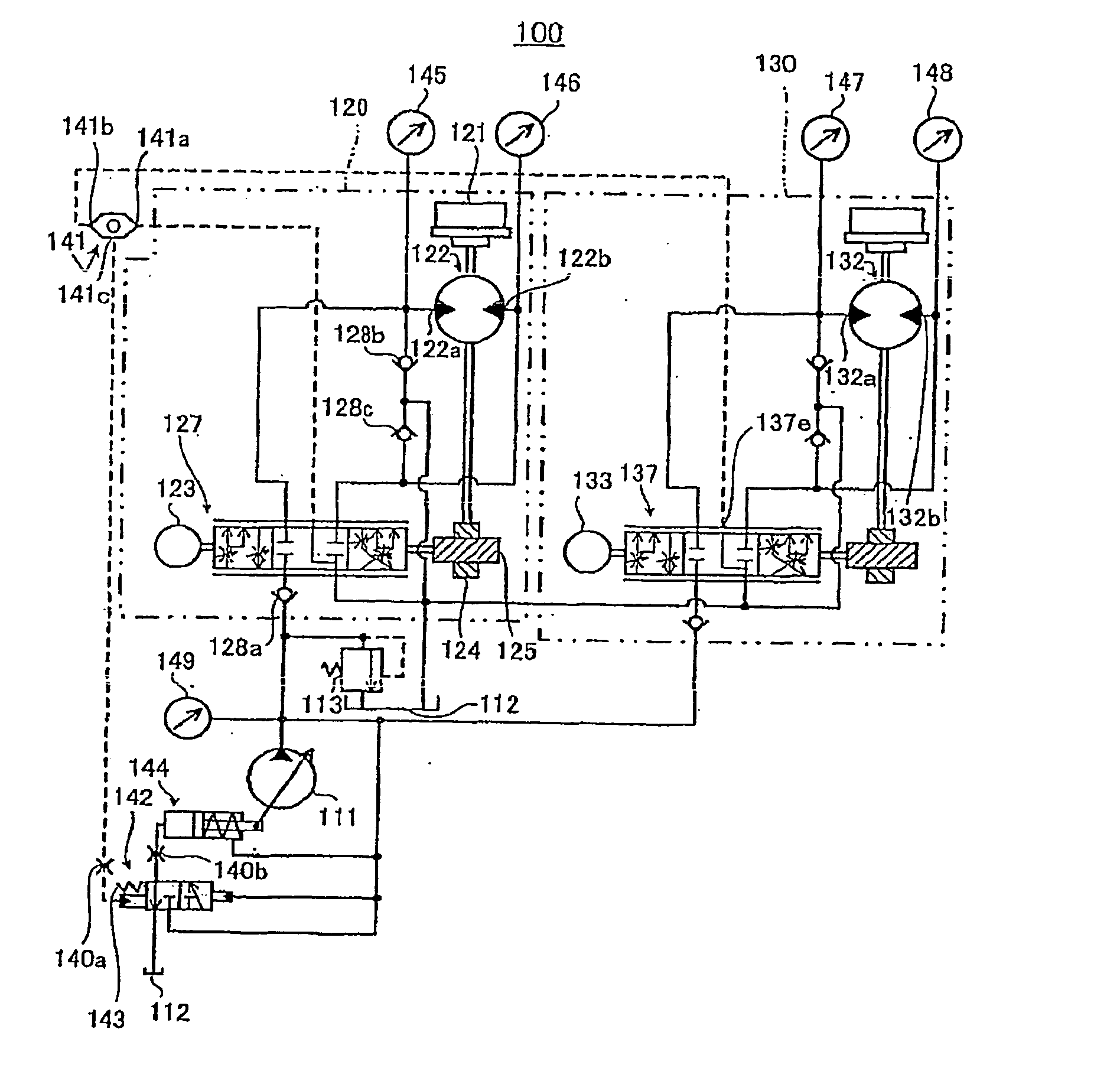
[0040] Firstly, the configuration of an electro-hydraulic actuation system according to a first embodiment will be described.

[0041] In FIGS. 1 to 3, an electro-hydraulic actuation system 100 as an electro-hydraulic actuation system according to the first embodiment includes a variable displacement hydraulic pump 111 as a pump of a constant horse power for discharging a working fluid (fluid), a tank 112 from which the working fluid is discharged and a relief valve 113 for keeping the working fluid discharge pressure of the variable displacement hydraulic pump 111 at a predetermined set pressure or lower.

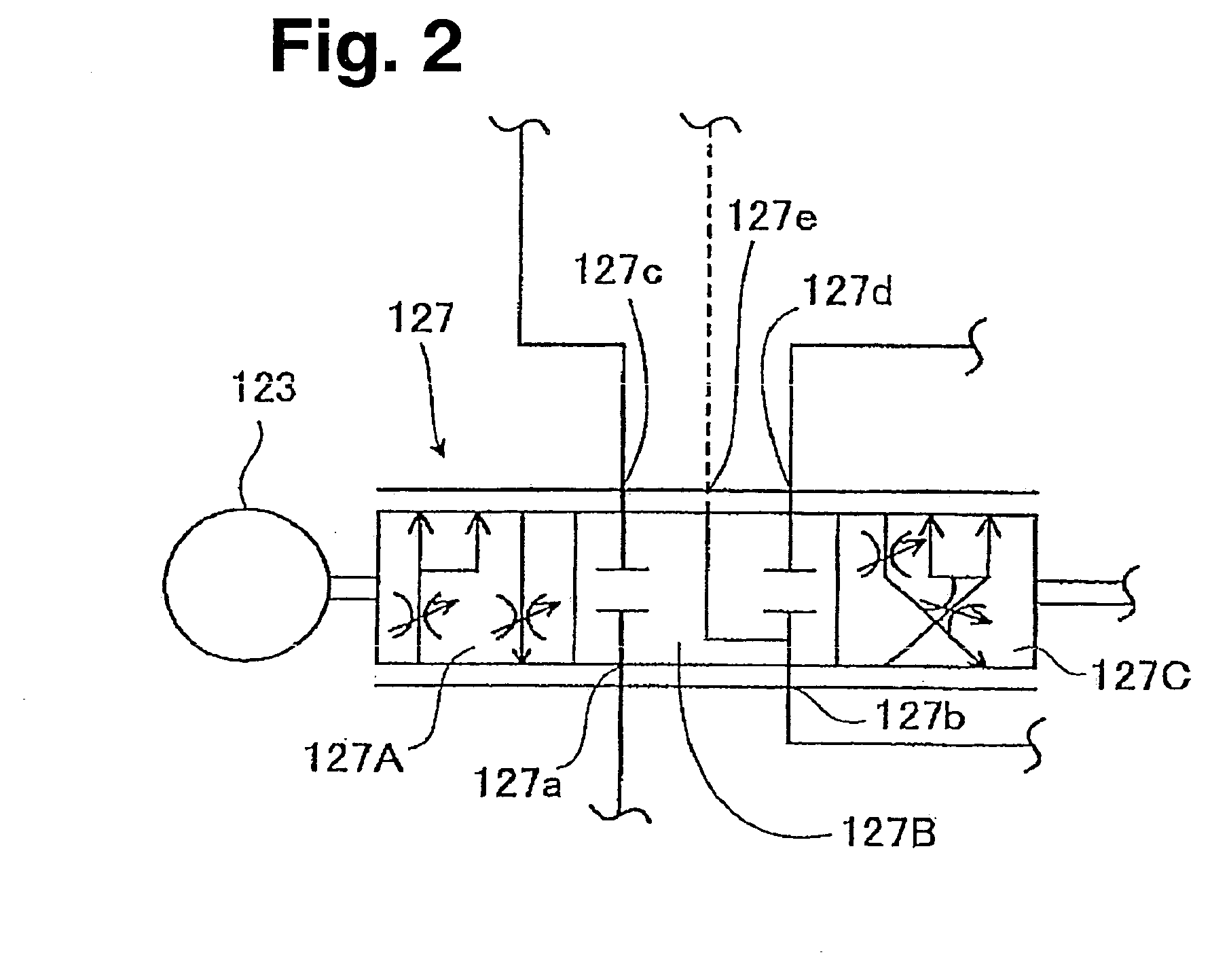
[0042] In addition, the electro-hydraulic actuation system 100 includes a unit (refer to FIGS. 4 to 7) as an electro-hydraulic actuator having reduction gears121 connected to a load not shown, a hydraulic motor 122 as a hydraulic actuator having formed therein a port 122a and a port 122b which are made to communicate with the variable displacement hydraulic pump 111 or the tank 112 ...

second embodiment

[0078] Firstly, the configuration of an electro-hydraulic actuation system according to a second embodiment will be described.

[0079] As shown in FIGS. 8 and 9, since an electro-hydraulic actuation system 300 as an electro-hydraulic actuation system according to the second embodiment has a substantially similar configuration to that of the electro-hydraulic actuation system (refer to FIG. 1) according to the first embodiment, hereinafter, like reference numerals are imparted to constituent parts of the electro-hydraulic actuation system 300 which are substantially like to those of the electro-hydraulic actuation system 100 and the detailed description thereof will be omitted.

[0080] Instead of the unit 120 (refer to FIG. 1) and the unit 130 (refer to FIG. 1) of the electro-hydraulic actuation system 100 (refer to FIG. 1), the electro-hydraulic actuation system 300 includes an electro-hydraulic actuator 320 (refer to FIGS. 10 to 14) and a unit 330, the detailed description of which w...

third embodiment

[0098] Firstly, the configuration of an electro-hydraulic actuation system according to a third embodiment will be described.

[0099] As shown in FIGS. 15 and 16, since an electro-hydraulic actuation system 500 as an electro-hydraulic actuation system according to the embodiment has a configuration which is substantially similar to that of the electro-hydraulic actuation system 100 (refer to FIG. 1) according to the first embodiment or the electro-hydraulic actuation system 300 (refer to FIG. 8) according to the second embodiment, hereinafter, like reference numerals are imparted to constituent parts of the electro-hydraulic actuation system 500 which are substantially like to those of the electro-hydraulic actuation system 100 or the electro-hydraulic actuation system 300, and the detailed description thereof will be omitted.

[0100] The electro-hydraulic actuation system 500 includes, as electro-hydraulic actuators, a unit 520 (refer to FIGS. 17 to 20) and a unit 530, the detailed d...


PUM


Abstract

An electrohydraulic actuation system in which the quantity of fluid being fed to hydraulic actuators under higher load pressure among those of a plurality of electrohydraulic actuators can be prevented from becoming deficient. In the electrohydraulic actuation system (100), a selection valve (141), a two-position valve (142), a spring (143) and a hydraulic cylinder (144) for altering delivery alter delivery of the working oil of a variable delivery hydraulic pump (111) based on the maximum pressure of the working oil being fed to hydraulic motors (122, 132) and the delivery pressure of working pump (111), and pressure gauges (145, 146, 147, 148, 149) and a computer (not shown) alter the rotatim speeds of motors (123, 133) at a substantially same rate for them.

Description

TECHNICAL FIELD [0001] The present invention relates to an electro-hydraulic actuation system for use in a hydraulic shovel or asphalt finisher and more particularly to an electro-hydraulic actuation system to which a load sensing system (hereinafter, referred to as LS) is applied for changing the discharge volume of a pump based on the load pressure of an actuator so that a differential pressure between the load pressure of the actuator and the discharge pressure of the pump becomes substantially constant. BACKGROUND ART [0002] Conventionally, as a hydraulic actuation system to which the LS is applied, there has been known, for example, a hydraulic actuation system 900 shown in FIG. 22. [0003] The hydraulic actuation system 900 includes a variable displacement hydraulic pump 911 for discharging a working fluid, a tank 912 from which the working fluid is discharged and a relief valve 913 for keeping the working fluid discharge pressure of the variable displacement hydraulic pump 911...

Claims


Application Information

Patent Timeline
Patent Type & Authority Applications(United States)
IPC IPC(8): F15B11/16F16D31/02
CPCF15B11/163F15B2211/78F15B2211/3111F15B2211/325F15B2211/327F15B2211/351F15B2211/353F15B2211/6054F15B2211/6313F15B2211/65F15B2211/7058F15B2211/71F15B2211/76F15B2211/763F15B2211/20553
Inventor ASANO, YOUJISHIMIZU, NOBUAKIKODAMA, HARUO
Owner NABLESCO CORP
Why Eureka
Try Eureka