Non-intrusive multiphase flow meter

a multi-phase flow meter and non-intrusive technology, applied in instruments, surveys, borehole/well accessories, etc., can solve the problems of equipment incapable of reliable and continuous downhole multi-phase flow measurement, severe limitation of its application, and equipment capable of withstanding harsh operation conditions

Inactive Publication Date: 2005-12-08
WEATHERFORD TECH HLDG LLC
View PDF11 Cites 25 Cited by
  • Summary
  • Abstract
  • Description
  • Claims
  • Application Information

AI Technical Summary

Problems solved by technology

This is particularly the case for high-cost deepwater developments and in complex multi-lateral wells.
Despite the potential value of real-time downhole multiphase flow data, the lack of equipment capable of reliable and continuous downhole multiphase flow measurements has severely limited its application.
Equipment capable of withstanding harsh operation conditions (e.g., extreme temperatures and pressures), have typically been limited to absolute temperature and pressure sensors.
Recently, however, a limited number of techniques have been developed to gather multiphase downhole flow data.
NFDs typically contain complex electronics for performing density measurements that may exhibit reliability and accuracy problems when subjected to downhole operating conditions.
Further, because the nuclear densitometers have a radioactive source, due to environmental issues, approvals may be required, and operating personnel may require extensive training.
However, these devices suffer from a number of disadvantages including restricted access below the device (which may prevent the running of tools below the device) and significant pressure loss due to the restrictive nature of the device.
Further, because these devices restrict flow of the mixture, loss of calibration is likely due to erosion and / or accumulation of deposits (e.g., of wax, asphaltenes, etc.).
These disadvantages may be compounded by poor resolution and accuracy of pressure sensors used to measure the pressure differences.

Method used


Image

  • Non-intrusive multiphase flow meter
  • Non-intrusive multiphase flow meter
  • Non-intrusive multiphase flow meter

Examples


Embodiment Construction

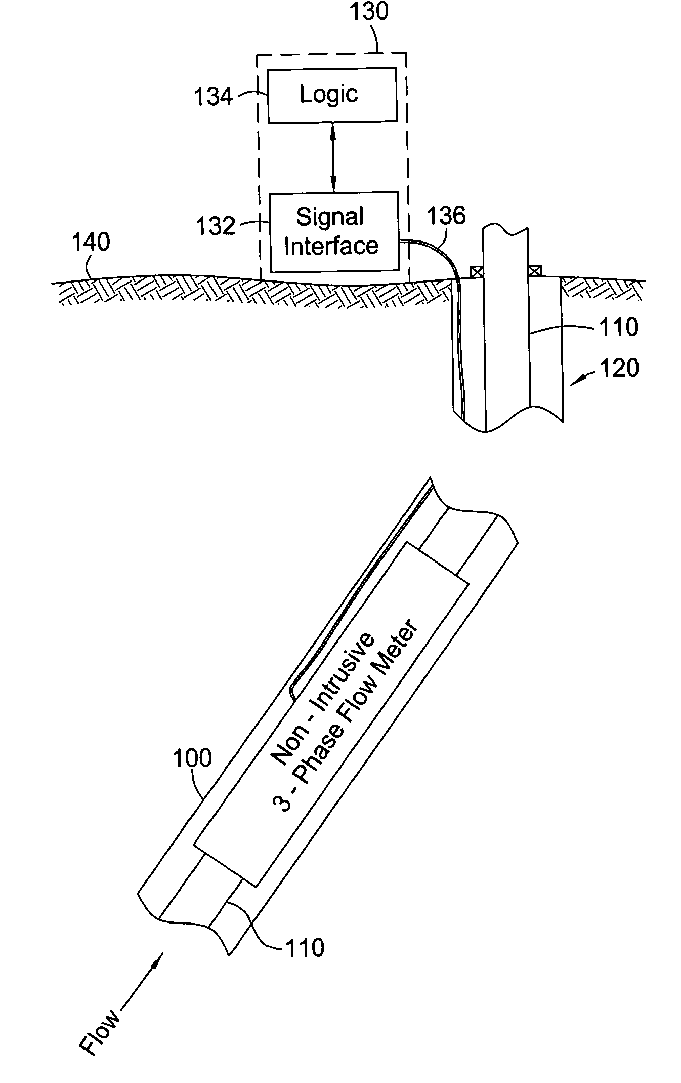
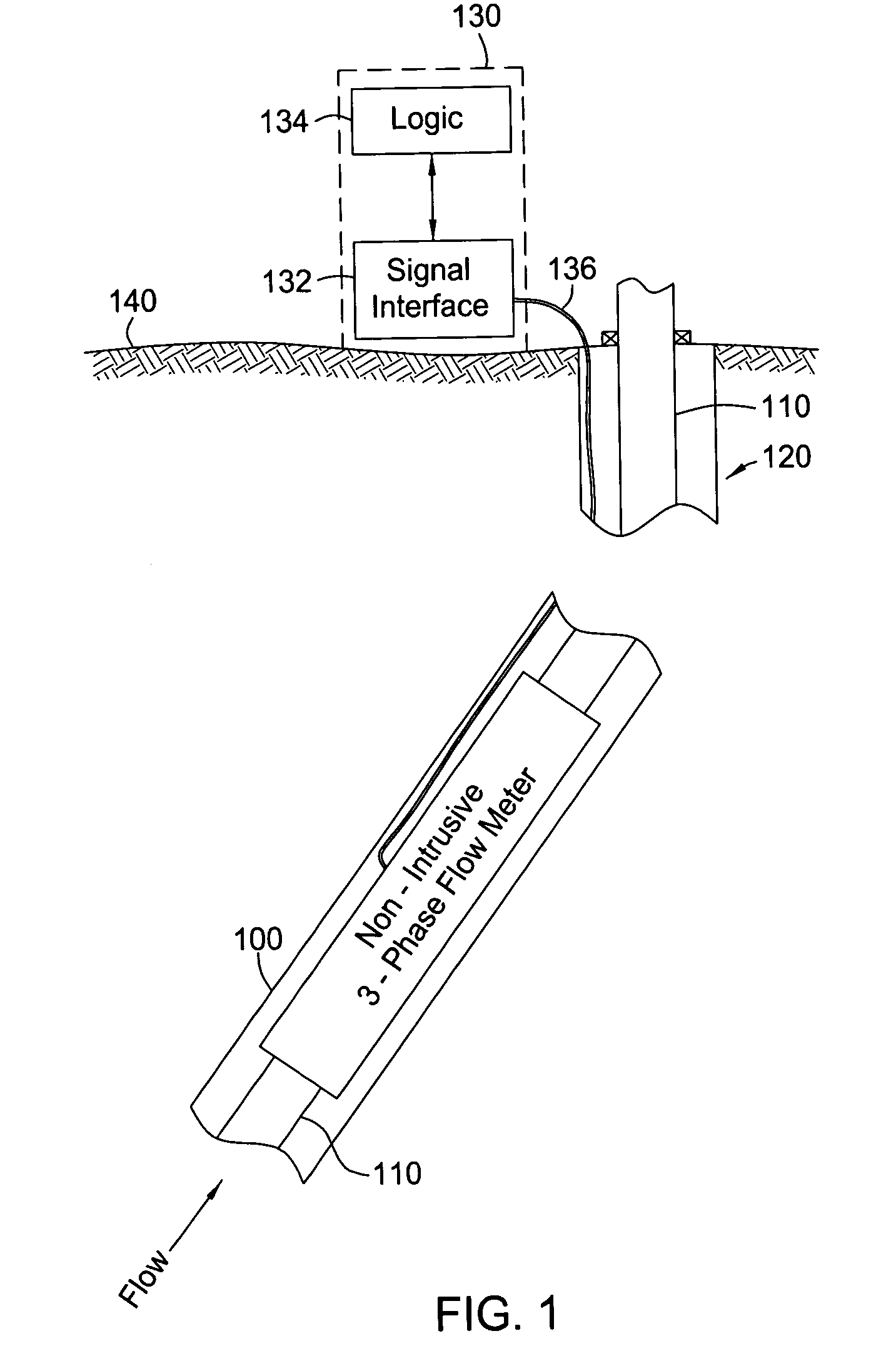
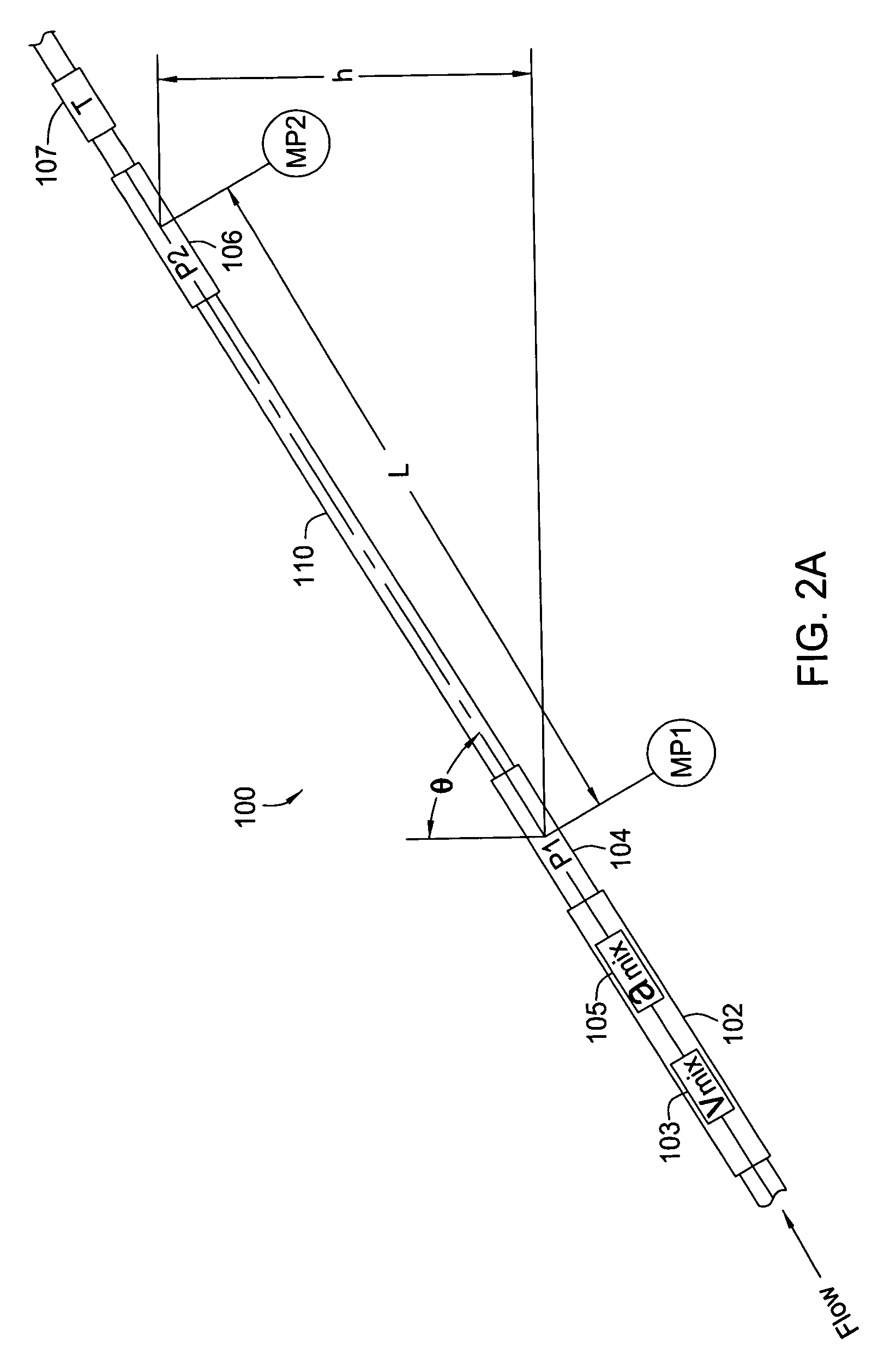
[0023] Embodiments of the present invention generally provide a method, apparatus, and system for determining volumetric fractions of individual phases of a multiphase mixture flowing through a pipe. In general, volumetric fractions and flow rates of the individual phases may be found using a determined mixture density and a measured speed of sound in the mixture. For some embodiments, the mixture density may be determined by direct measurement from a densitometer. For other embodiments, the mixture density may be determined based on a measured pressure difference between two vertically displaced measurement points and a measured bulk velocity of the mixture. Accordingly, such embodiments may utilize various arrangements of non-intrusive pressure sensors, velocity sensors, and speed of sound sensors, thereby overcoming the previously described disadvantages of intrusive devices, such as Venturi flow meters.

[0024] As used herein, the term density generally refers to volumetric densi...


PUM

PropertyMeasurementUnit
densityaaaaaaaaaa
speedaaaaaaaaaa
pressureaaaaaaaaaa

Abstract

Embodiments of the present invention generally provide methods, apparatus, and systems for determining void fractions of individual phase components of a multiphase mixture. The void fractions may be determined based on measured parameters of the mixture as a whole, such as differential pressure, bulk velocity of the mixture and speed of sound in the mixture. According to some embodiments, the mixture parameters may be measured using non-intrusive fiber optic based sensors. Various other parameters may also be derived from the void fractions, such as individual phase flow rates, liquid holdup and watercut parameters (for oil and gas mixtures).

Description

CROSS-REFERENCE TO RELATED APPLICATIONS [0001] This application is a continuation of co-pending U.S. patent application Ser. No. 10 / 348,040, filed Jan. 21, 2003. The aforementioned related patent application is herein incorporated by reference.BACKGROUND OF THE INVENTION [0002] 1. Field of the Invention [0003] Embodiments of the present invention generally relate to downhole production operations and particularly to measuring volumetric fractions of individual phases of a multiphase mixture. [0004] 2. Description of the Related Art [0005] Producing oil and gas wells typically provide a multiphase mixture of oil, gas, and water. Real-time, downhole flow data regarding the mixture (e.g., flow rate of the mixture, individual phase flow rates and fractional phase volumes, also referred to as “void fractions”) is widely acknowledged to be of significant value for production optimization. This is particularly the case for high-cost deepwater developments and in complex multi-lateral wells...

Claims


Application Information

Patent Timeline
Patent Type & Authority Applications(United States)
IPC IPC(8): E21B47/10G01N9/26G01N9/36G01N29/024G01N33/28
CPCE21B47/10G01N9/26G01N9/36G01N2291/02818G01N33/2823G01N2291/024G01N2291/02433G01N29/024E21B47/107
Inventor JOHANSEN, ESPEN S.
Owner WEATHERFORD TECH HLDG LLC
Why Eureka
Try Eureka