Displaying instrument and luminous pointer
- Summary
- Abstract
- Description
- Claims
- Application Information
AI Technical Summary
Benefits of technology
Problems solved by technology
Method used
Image
Examples
first embodiment
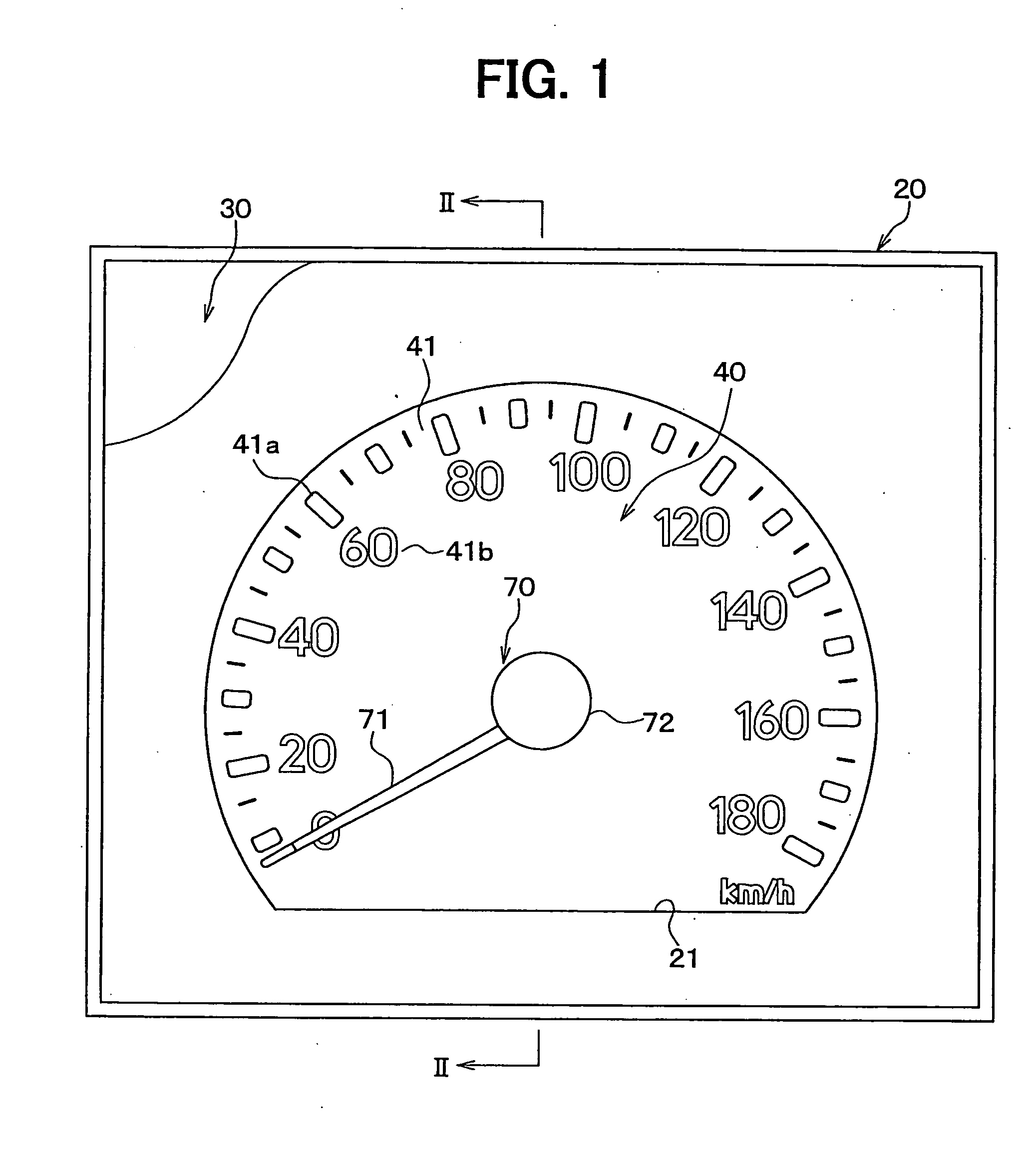
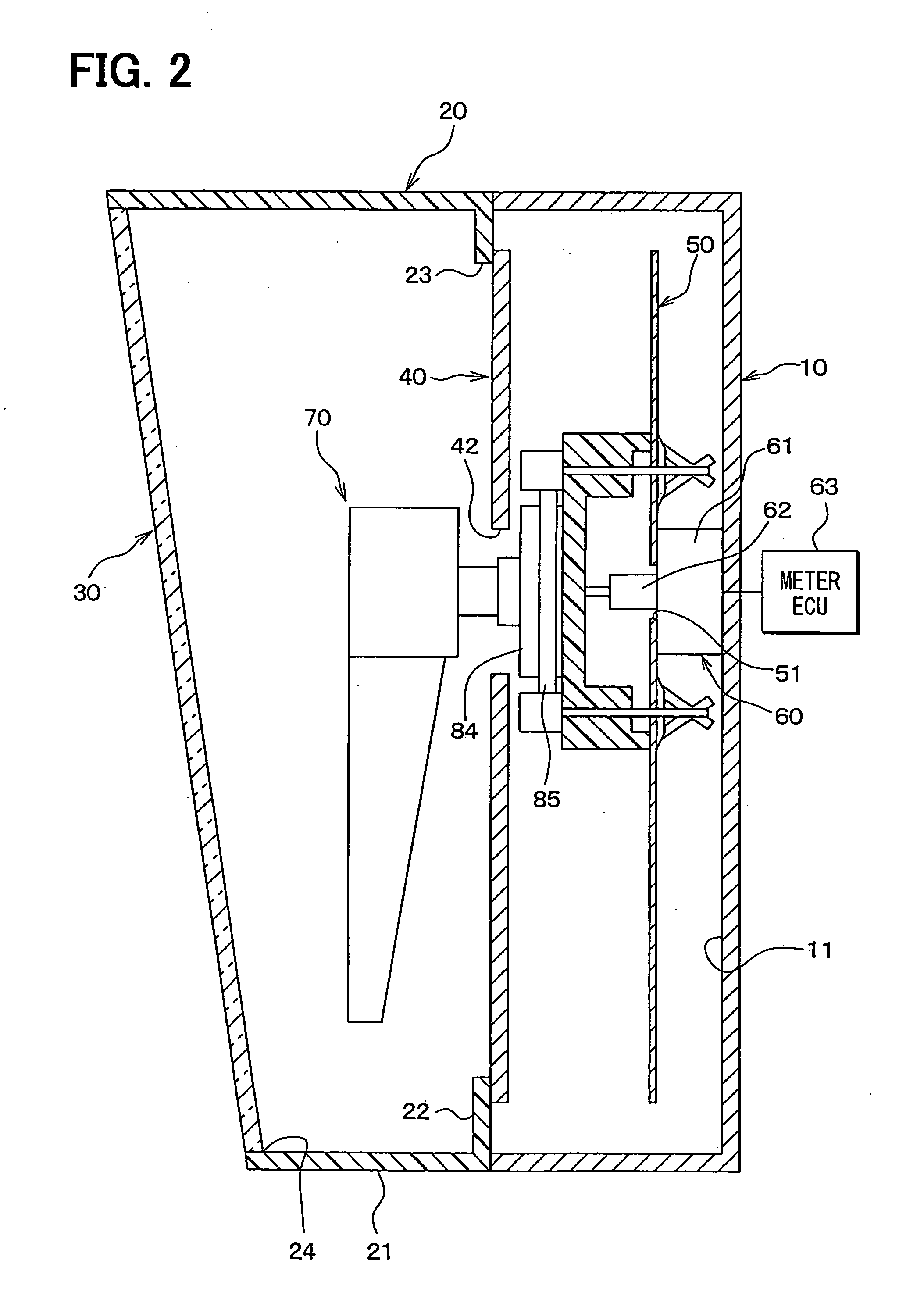
[0026] A displaying instrument having a luminous pointer applied to a speedometer will be discussed. A front view of the speedometer is shown in FIG. 1 and a cross-sectional view of the speedometer sectioned by the II-II line in FIG. 1 is shown in FIG. 2. Referring to FIGS. 1 and 2, a speedometer includes a case 10, a hood 20, a front panel 30, a dial plate 40, a circuit board 50, a movement 60, and a luminous pointer 70. The case 10, the hood 20, and the front panel 30 form a housing, and the dial plate 40, the circuit board 50, the movement 60, and the pointer 70 are assembled to the housing.
[0027] The case 10 has a U-shaped cross-section and the movement 60 is fixed to the case 10 at a position corresponding a base of the U. The hood 20 formed in a frame-shape has a surrounding wall 21 and a base wall 22. The base wall 22 has a rear opening 23 for the dial plate 40 and the luminous pointer 70 to be viewed from the front. The front panel 30 provided as a black face having about 2...
second embodiment
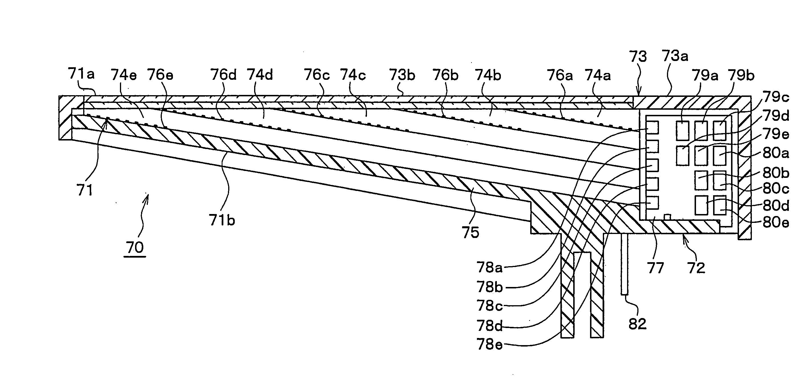
[0042] Referring to FIG. 7, a pointer body 171 of a luminous pointer 170 is formed such that a top surface 171a is sloped with respect to the top surface of the dial plate 40 and a rear surface 171b is parallel to the top surface of the dial plate 40. With this configuration, the same effects as the first embodiment can be produced. Prisms 174a-174e are arranged such that their bottom surfaces are parallel to a bottom surface 171b of the pointer body 171. The first ends of the prisms 174a-174e are exposed on the boss side, and the second ends of the prisms 174a-174e are shaped at angles to become parallel to the top surface 171a. The second ends are on the same plane, and the pointer 170 is assembled by sandwiching the prisms 174a-174e between the pointer body 171, a base portion 175 of a boss 172, and the cover 73.
third embodiment
[0043] A front view of a speedometer is shown in FIG. 8, and a cross-sectional view of the speedometer sectioned by the IX-IX line in FIG. 8. The speedometer includes a display unit 90 having a display screen 91 for displaying information and semi-reflecting semi-transparent half mirror 92 for reflecting contents of the information displayed on the screen 91. Information is displayed on the display screen 91 through control performed by the meter ECU 63. The contents of the information are reflected by the half mirror 92 so that the driver can see them. A light emitting circuit randomly drives the LEDs 78a-78e, for example, by turning on and off the LEDs 78a-78e with switching components.
[0044] The contents of the information may not be easily seen by the driver when they overlaps with the pointer 70. Thus, the pointer 70 is not illuminated in areas that overlaps with areas in which contents of information are reflected by the half mirror 92 when the contents are displayed. For exa...
PUM
 Abstract
Description
Claims
Application Information
 - R&D
- Intellectual Property
- Life Sciences
- Materials
- Tech Scout
- Unparalleled Data Quality
- Higher Quality Content
- 60% Fewer Hallucinations
Browse by: Latest US Patents, China's latest patents, Technical Efficacy Thesaurus, Application Domain, Technology Topic, Popular Technical Reports.
© 2025 PatSnap. All rights reserved.Legal|Privacy policy|Modern Slavery Act Transparency Statement|Sitemap|About US| Contact US: help@patsnap.com


