Roman blind structure

Inactive Publication Date: 2005-12-08
NIEN LESLIE
View PDF4 Cites 13 Cited by
  • Summary
  • Abstract
  • Description
  • Claims
  • Application Information

AI Technical Summary

Benefits of technology

[0004] It is, therefore, the primary purpose of the present invention to provide a Roman blind structure, including a telescopic upper beam of a Roman blind, and a blind body of a proper length and width fixedly attached to the underside of the telescopic upper beam thereof wherein the blind body is provided with a plurality of long tubular tunnels equidistantly folded and seamed from top to bottom at one side thereof for adjustable rods, each having a plurality of dividing grooves properly cut in equal space at the surface thereon, to be adapted therein respectively; whereby, when the telescopic upper beam is properly adjusted to fit to a window frame, the adjustable rods are directly bent downwards by force along the dividing grooves thereof to break off extra sections of the adjustable rods thereof without any other tools applied thereto, facilitating an easy and speedy assembly thereof.
[0005] It is, therefore, the second purpose of the present invention to provide a Roman blind structure wherein a plurality of retaining members each having a clamping part dispo

Problems solved by technology

There are some drawbacks to such conventional Roman blind structure.
Thus, the conventional blind structure is quite limited in practical use and reduced in the competitive power thereof.
Second, in case the Roma

Method used


Image

  • Roman blind structure
  • Roman blind structure
  • Roman blind structure

Examples


Example

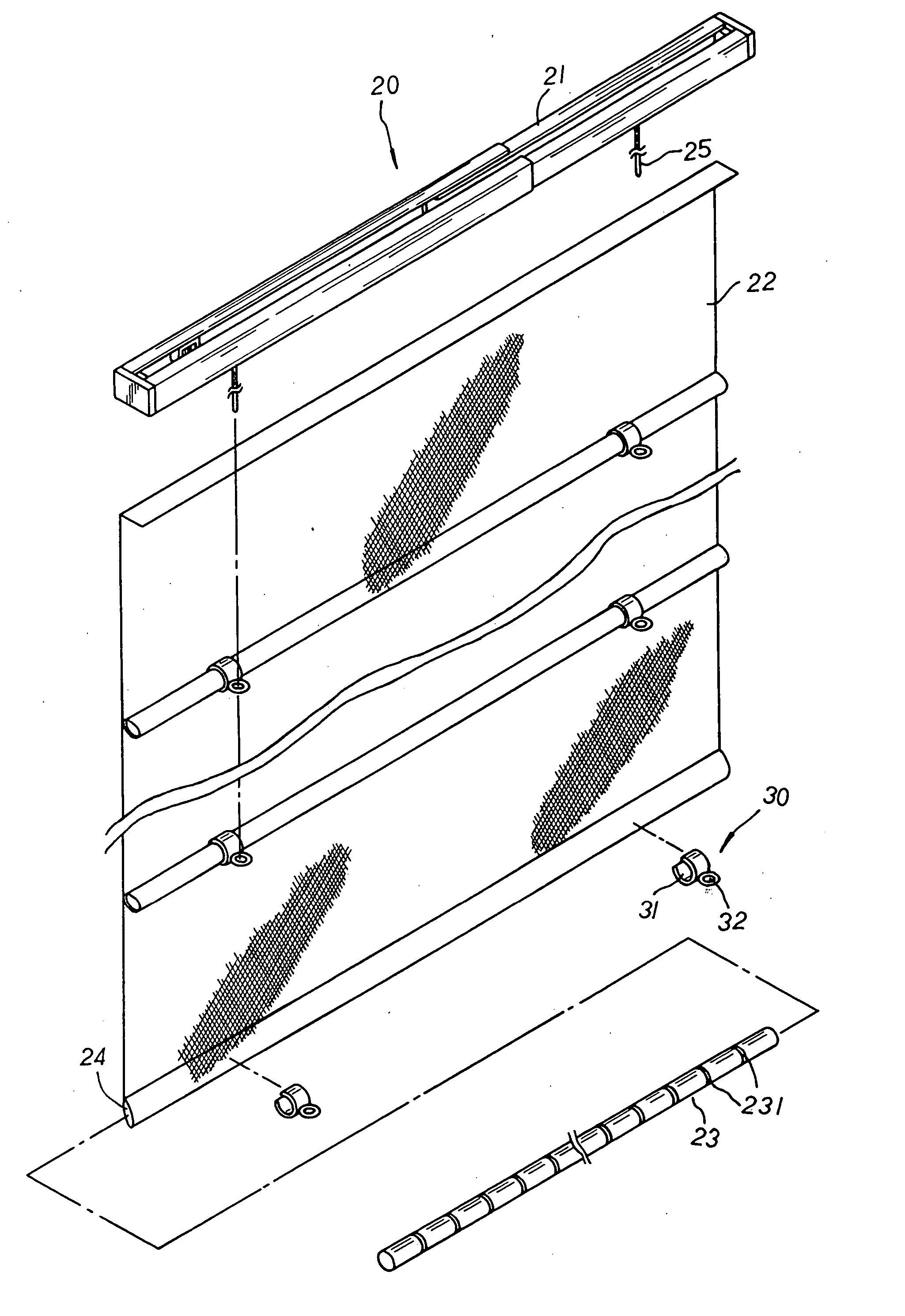
[0012] Please refer to FIG. 3. The present invention is related to a Roman blind structure, including a Roman blind 20 made up of a telescopic upper beam 21, and a blind body 22 of a proper length and width fixedly attached to the underside of the telescopic upper beam 21 thereof. The blind body 22 is equidistantly folded backwards for a certain length into double layers and sequentially seamed up from top to bottom at one side thereof to provide a plurality of long tubular tunnels 24 each for an adjustable rod 23 to be located therein. The adjustable rod 23 is provided with a plurality of dividing grooves 231 properly cut in equal space at the surface thereon. At preset positions of the left and right sides of each long tubular tunnel 24 are respectively located a retaining member 30 with a C-shaped clamping part 31 extending at one side thereof in conformance to the outer diameter of the adjustable rod 23 to synchronically clamp tight the adjustable rod 23 adapted inside the long ...


PUM


Abstract

A Roman blind structure includes a Roman blind made up of a telescopic upper beam, and a blind body of a proper length and width fixedly attached to the underside of the telescopic upper beam thereof wherein the blind body is provided with a plurality of long tubular tunnels equidistantly folded and seamed up from top to bottom at one side thereof for adjustable rods, each having a plurality of dividing grooves properly cut in equal space at the surface thereon, to be adapted therein respectively. At preset positions of the left and right sides of each long tubular tunnel are respectively located a retaining member with a C-shaped clamping part extending at one side thereof to clamp tight the adjustable rod adapted inside the long tubular tunnel thereby, and the retaining members are also equipped with cord-passage holes, each protruding levelly at one side of the C-shaped clamping part thereof, for pull cords to be sequentially led there-through before fixedly tied up to the bottommost cord-passage holes thereof. When the telescopic upper beam is properly adjusted to fit to a window frame, the adjustable rods are directly bent downwards by force along the dividing grooves to break off extra sections of the adjustable rods thereof without any other tools applied thereto, and an extra part of the adjusted blind body is collected either at the middle section or at both the left/right sides of the adjustable rods in wavy wrinkles, achieving versatile visual effects of the Roman blind as well as facilitating an easy and speedy assembly of the present invention.

Description

BACKGROUND OF THE INVENTION [0001] The present invention is related to a Roman blind structure, including a telescopic upper beam of a Roman blind, and a blind body of a proper length and width fixedly attached to the underside of the telescopic upper beam thereof wherein the blind body is provided with a plurality of long tubular tunnels equidistantly folded and seamed from top to bottom at one side thereof for adjustable rods, each having a plurality of dividing grooves properly cut in equal space at the surface thereon, to be adapted therein respectively; whereby, when the telescopic upper beam is properly adjusted to fit to a window frame, the adjustable rods are directly bent downwards by force along the dividing grooves thereof to break off extra sections of the adjustable rods thereof without any other tools applied thereto, and an extra part of the adjusted blind body is collected either at the middle section or both the left / right sides of the adjustable rods in wavy wrinkl...

Claims


Application Information

Patent Timeline
IPC IPC(8): A47H5/14E06B9/262E06B9/38
CPCE06B9/262E06B2009/2622E06B9/38
Inventor NIEN, LESLIE
Owner NIEN LESLIE
Why Eureka
Try Eureka