
Ornithopter with independently controlled wings

an ornithopter and independently controlled technology, applied in the field of aeronautical equipment, can solve the problems of inability to hover, inability to control at low speeds, and inability to achieve hover, so as to maneuver effectively, and increase the maneuverability of the ornithopter

Inactive Publication Date: 2005-12-08
CHRONISTER NATHAN JEFFREY
View PDF8 Cites 55 Cited by
  • Summary
  • Abstract
  • Description
  • Claims
  • Application Information

AI Technical Summary

Benefits of technology

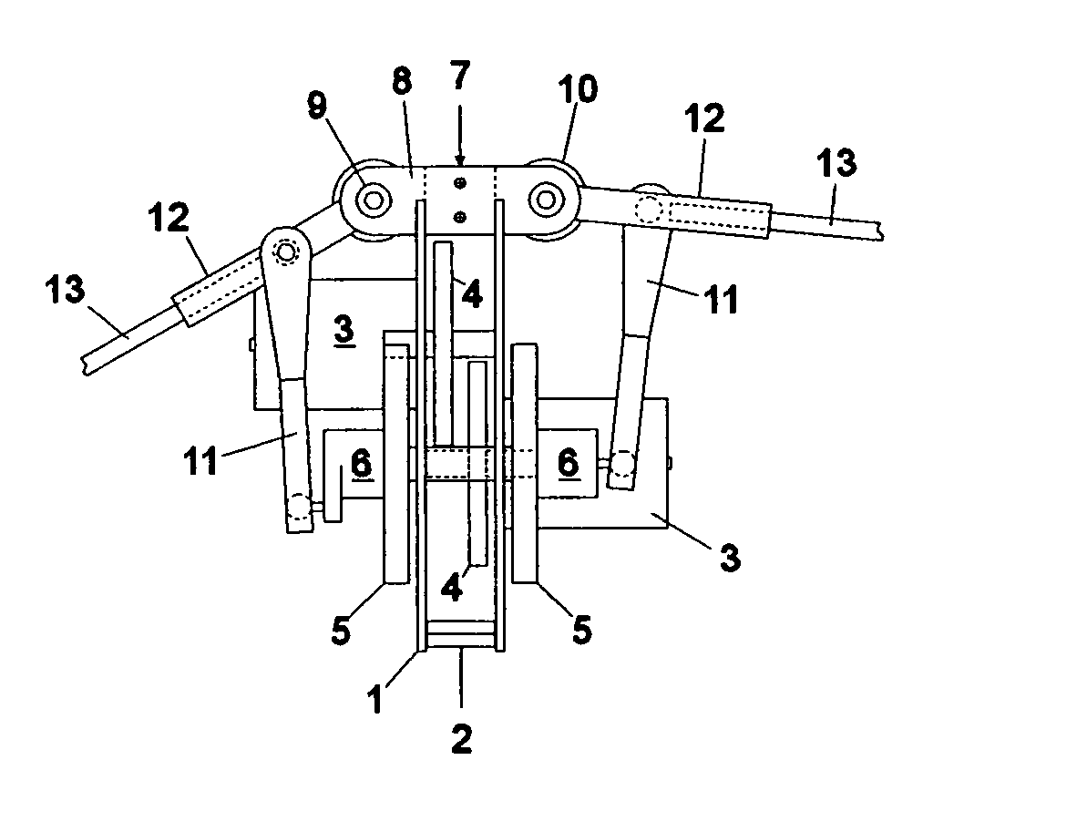
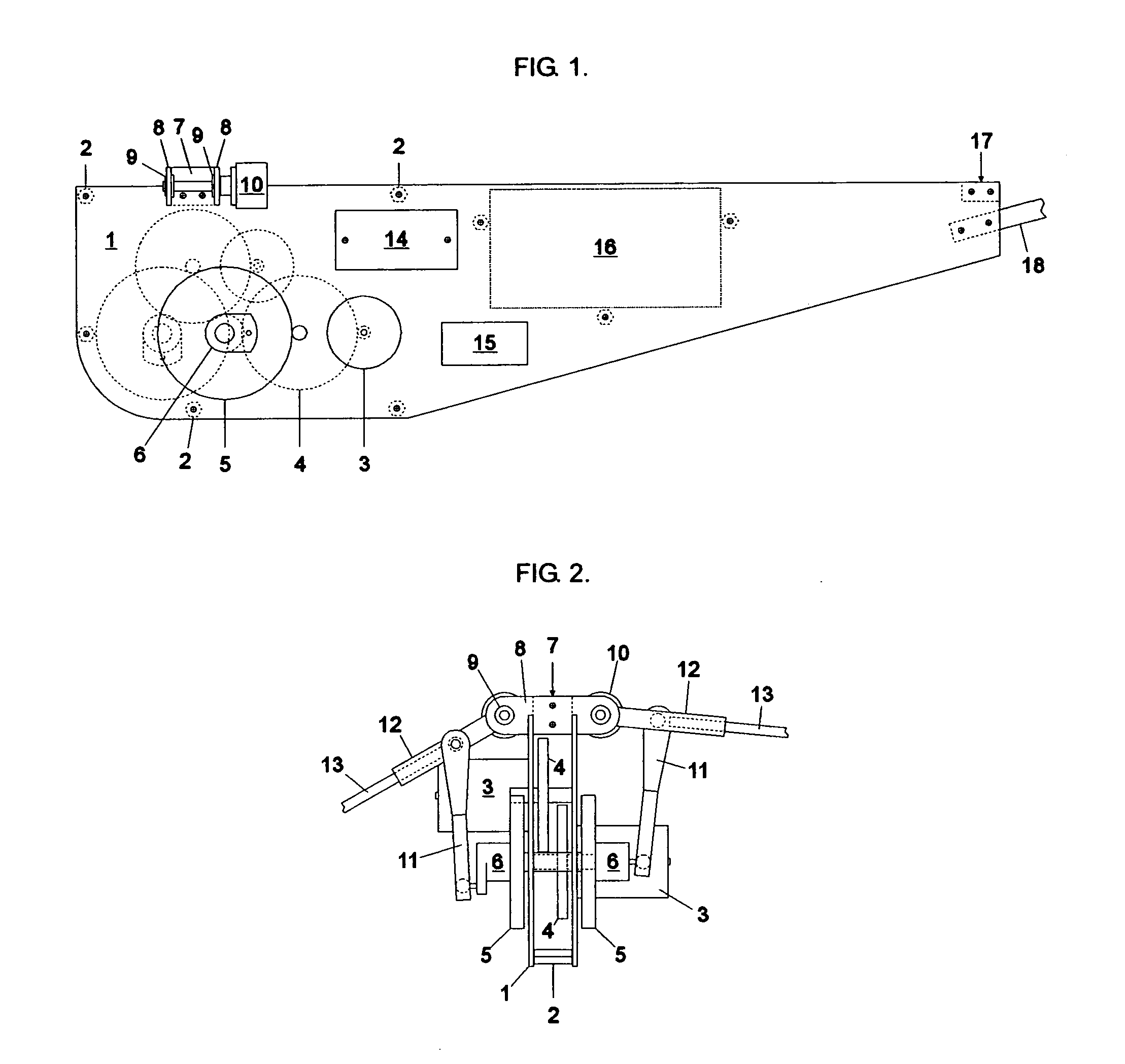
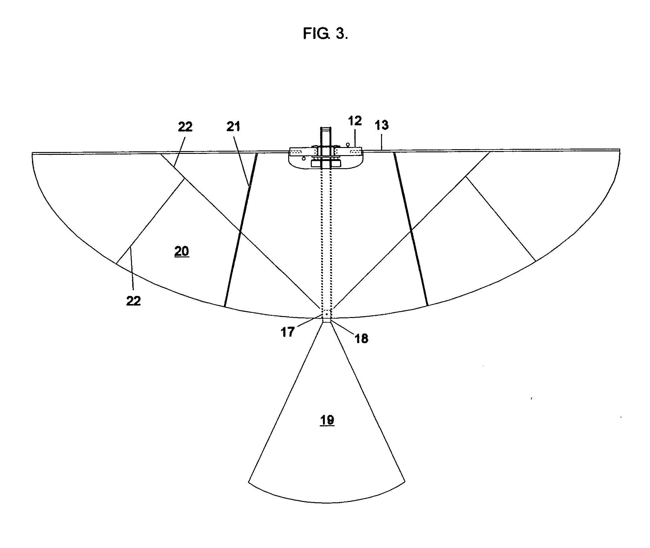
[0012] The claimed invention is an ornithopter in which the wings can be controlled independently of each other, and their speed varied throughout the stroke, in order to control the flight of the aircraft and perform aerobatic maneuvers. Asymmetry of the wing flapping action is used to provide directional control. A microprocessor monitors the position of each wing and receives commands from a radio control receiver. The processor also controls two motors, which drive the left and right wings. This invention is intended to offer much greater maneuvering or steering forces than can be generated by a hinged tail assembly, thereby greatly increasing the maneuverability of the ornithopter and allowing it to maneuver effectively at lower speeds and when hovering.

Problems solved by technology

Control becomes ineffective at low speeds as the ornithopter approaches hovering flight.
This inability to hover limits the practical application of current ornithopter designs.
It is considered undesirable to have an imbalance of the right and left wings, which would interfere with the action of the tail or other control surfaces.
In these cases, however, the asymmetric flapping of the wings is not used for flight control.
However, that potential has not been realizd in current designs.

Method used


Image

  • Ornithopter with independently controlled wings
  • Ornithopter with independently controlled wings
  • Ornithopter with independently controlled wings

Examples


Embodiment Construction

—PREFERRED EMBODIMENT

[0018] Typical ornithopter flight control systems include a radio receiver, an electronic speed control for the drive motor, and two servos. The servos control the flight path by moving a planar tail surface, or sometimes by moving an elevator and rudder like those used in radio controlled airplanes. This system provides a means of directional control, but the maneuverability of the ornithopter is limited.

[0019] In the invention described here, the wings rather than tail provide the maneuvering forces. This is achieved by using a separate motor and geartrain for each wing, controlled by a microprocessor. This allows the wings to move independently of each other, for steering, and it allows the wing flapping speed to vary systematically in different parts of the flapping cycle, in order to control the pitch of the aircraft. This system allows much greater maneuverability, particularly at low speeds where tail surfaces are not very effective. It also introduces n...


PUM


Abstract

The invention described here offers a more effective method of ornithopter flight control. To accomplish this, the ornithopter has dual microprocessor-controlled drive systems for flapping the wings independently of each other. Various wing movements can cause the ornithopter to turn, roll, or pitch up or down. Weight and complexity are reduced by eliminating the need for servo-controlled tail surfaces.

Description

CROSS-REFERENCE TO RELATED APPLICATIONS [0001] This application claims the benefit of Provisional Patent Application Ser. No. 60 / 577,882, filed Jun. 8th, 2004 by the present inventor.STATEMENT REGARDING FEDERALLY SPONSORED RESEARCH OR DEVELOPMENT [0002] Not Applicable. REFERENCE TO SEQUENCE LISTING, A TABLE, OR A COMPUTER PROGRAM LISTING COMPACT DISC APPENDIX [0003] Not Applicable. BACKGROUND OF THE INVENTION [0004] 1. Field of Invention [0005] This invention pertains to the field of aeronautics and describes an aircraft sustained by beating wings (Class 244, Subclass 22). [0006] 2. Prior Art [0007] Radio-controlled ornithopters, or flapping-wing aircraft, are becoming popular among radio-control hobby enthusiasts. Ornithopters are also being considered for use in aerial reconnaissance. In both roles, increased maneuverability is desirable. Ornithopters currently use a conventional rudder and elevator control system, or a moveable stabilizer that can be tilted left and right for ste...

Claims


Application Information

Patent Timeline
IPC IPC(8): B64C33/00B64C33/02B64C39/02
CPCB64C33/02B64C39/028B64C2201/146B64C2201/042B64C2201/141B64C2201/025B64U10/40B64U2201/10B64U50/19B64U2201/20
Inventor CHRONISTER, NATHAN JEFFREY
Owner CHRONISTER NATHAN JEFFREY
Learn More