Body worn physiological sensor device having a disposable electrode module

a sensor device and electrode module technology, applied in the field of physiological monitors, can solve the problems of tangled wires, inability to do any of the traditional ecg analysis functions, and inability to use sensors

Active Publication Date: 2012-07-03
WELCH ALLYN INC
View PDF121 Cites 393 Cited by
  • Summary
  • Abstract
  • Description
  • Claims
  • Application Information

AI Technical Summary

Problems solved by technology

Such units generally measure only heart beat and are not capable of doing any of the traditional ECG analysis functions.
A recurrent problem with the portable monitors typically used in healthcare applications is the need for wires from sensors situated on the patient's body to the portable unit.
These wires can become tangled and cause discomfort or become unplugged when inadvertently pulled or tugged on.
In addition, wire motion can increase ECG noise due to the triboelectric effect.
Muscle movement can also increase ECG noise, due to the typical placement of ECG electrodes over major muscles.
Moreover, portable monitor battery maintenance (e.g. battery recharging or replacement) can be time consuming and costly.
Another problem is related to the requirement that a medical grade monitor survive multiple defibrillation cycles of at least 360 joules.
The problem is that the physical volume of conventional power resistors is too large for use in a compact monitor application.
Another shortcoming of small sensor devices is that these devices lack the intelligence to vary the amount and type of data transmitted, depending on patient condition.
While transmitting the full patient waveform is the preferred solution from a purely clinical standpoint, such transmission requires significant power to transmit large amounts of data and restricts the design from being small and inexpensive.
Yet another problem is that arrhythmia analysis is a computationally intensive operation not well-suited to existing small portable monitors that presently have no ability to perform arrhythmia analysis.

Method used


Image

  • Body worn physiological sensor device having a disposable electrode module
  • Body worn physiological sensor device having a disposable electrode module
  • Body worn physiological sensor device having a disposable electrode module

Examples


Embodiment Construction

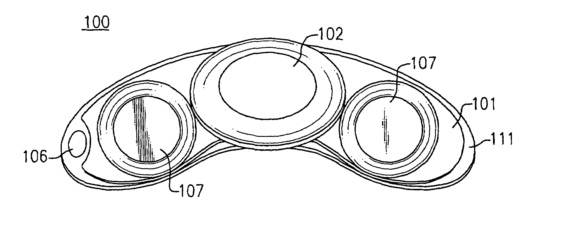
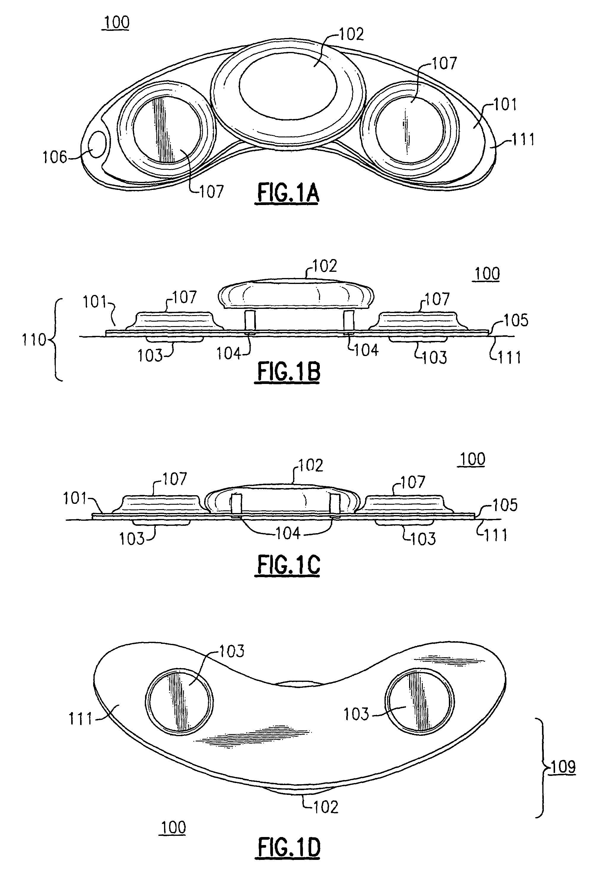
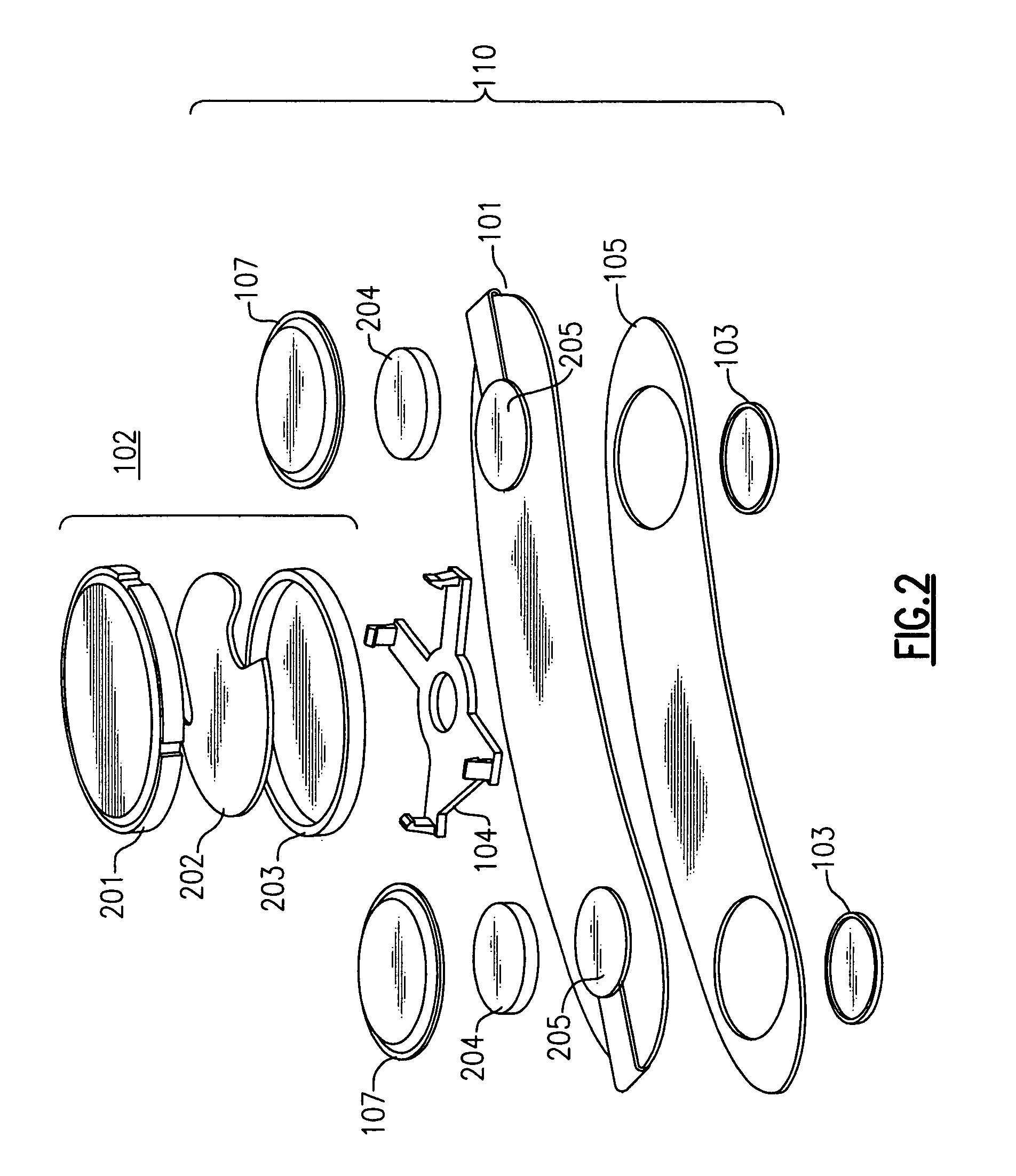
[0040]A “body worn” device is described herein with regard to certain exemplary embodiments. A “body worn” device is defined herein as a device that is directly, but non-permanently, affixed to a patient's body. A “body worn monitor” is a device that can be directly “worn” on the patient's body as a single unit, including one or more physiological sensors and a communications and computation module to perform at least initial processing of one or more physiological measurements made using one or more physiological sensors. Unlike prior art patient-wearable devices, at least one sensor can be incorporated into the device that makes a direct or indirect (such as by capacitive coupling) electrical connection with the patient's body without the use of external wires from sensors to the device. In addition and unlike athletic heart monitors, a “body worn” monitor can be a full functioning medical grade monitor, e.g. meeting the requirements of European Unions' Medical Device Directive an...


PUM


Abstract

A body worn patient monitoring device includes at least one disposable module including a plurality of electrical connections to the body. The body worn patient monitoring device also includes at least one communication-computation module, the communication-computation module having at least one microprocessor to actively monitor the patient and to perform a real-time physiological analysis of the physiological signals. A radio circuit communicates a raw physiological signal or a result of the physiological analysis at a predetermined time or on the occurrence of a predetermined event, via a radio transmission to a remote radio receiver, wherein the at least one disposable module is mechanically and electrically coupled directly to the at least one communication-computation module. The body worn patient monitoring device, including the at least one disposable module and the at least one communication-computation module, is directly non-permanently affixed to the skin surface of the patient.

Description

FIELD OF THE INVENTION[0001]This invention relates generally to a physiological monitor and more particularly to a body worn physiological monitor.BACKGROUND OF THE INVENTION[0002]Measurements of various physiological parameters are important to the study of the human condition. Physiological measurements can be particularly important in a health care setting, such as in a hospital. One of the more important physiological measurements performed on a patient is the electrocardiogram (ECG), showing the condition of the human heart.[0003]Portable patient monitors have evolved that allow patients to enjoy at least some mobility. Typically a battery operated monitor can be hung on a belt, shoulder strap, or carried by a patient using some other similar hanging arrangement. Sensors, such as ECG electrodes, are affixed to the patient's body, such as with tape, and connected to the battery operated monitor by wires. After a fixed interval of time, or at a low battery indication, the batteri...

Claims


Application Information

Patent Timeline
Patent Type & Authority Patents(United States)
IPC IPC(8): A61N1/00A61B5/04A61B5/308A61B5/274
CPCA61B5/0006A61B5/04085A61B5/04282A61B5/0416A61B5/0816A61B5/14552A61B5/742A61B5/746A61B5/04087A61B5/04286A61B2560/0209A61B2560/0412A61B5/7232A61B5/68335A61B5/282A61B5/303A61B5/316A61B5/259A61B5/274A61B5/301A61B5/14542A61B2560/0214A61B2562/0214A61B2562/182A61B5/024A61B5/02438
Inventor BAKER, STEVEN D.MCADAMS, ERIC T.WELCH, JAMES P.OHLENBUSCH, NORBERTBLACKADAR, THOMAS P.
Owner WELCH ALLYN INC
Why Eureka
Try Eureka