Internal permanent magnet rotor having improved configuration of magnetic flux barriers

a technology of internal permanent magnets and rotors, which is applied in the direction of magnetic circuit rotating parts, dynamo-electric machines, magnetic circuit shape/form/construction, etc., can solve the problems of increasing the manufacturing cost of such machines, increasing the total cost of the permanent magnets used in each machine by comparison with that of a usual type of ipm rotary electric machin

Inactive Publication Date: 2005-12-08
DENSO CORP
View PDF7 Cites 47 Cited by
  • Summary
  • Abstract
  • Description
  • Claims
  • Application Information

AI Technical Summary

Benefits of technology

[0018] As a result of such a configuration of the circumferentially disposed flux barriers of the permanent magnet it can be ensured that when q-axis magnetic flux flows from the stator into the rotor core and then passes through the rotor core along path below a permanent magnet, before returning to the circumferential face of the rotor core, the q-axis magnetic flux flow is effectively prevented from being diverted by flowing into the permanent magnet. It can thereby be ensured that, when for example the IPM rotary electric machine is operated as an electrical generator, a higher level of output power can be achieved under a condition of high-speed rotation than has been possible in the prior art, without requiring an increase in the number of permanent magnets installed in the rotor, or the use of more expensive permanent magnets that produce a higher level of magnetic flux. In addition, this result is achieved without requiring any increased complexity in configuration of the rotor, so that increased manufacturing cost is avoided.
[0023] With such a configuration of each circumferential flux barrier, in addition to the amount of q-axis magnetic flux that is diverted to each permanent magnet being reduced as described above, the length of path along which q-axis magnetic flux flows within the rotor before returning to the stator can be reduced, so that an increase can be achieved in the maximum level of power produced before the onset of saturation.

Problems solved by technology

Such prior art types of IPM rotary electric machine utilize permanent magnets that are formed of expensive materials such as rare earths, thereby increasing the manufacturing costs of such machines.
In addition, such prior art types of IPM rotary electric machine have various disadvantages, as described in the following In the case of the rotary electric machines proposed in reference documents 1 and 2, two permanent magnets are utilized to form each pole of the rotary electric machine, so that the manufacturing operations to produce the rotor of such a machine are complex, and the total cost of the permanent magnets used in each machine is increased by comparison with that of a usual type of IPM rotary electric machine.
However due to the fact that priority is given to increasing the flow of the q-axis magnetic flux, the shape of each permanent magnet (and hence, the shape of each of the magnet accommodation cavities within which the permanent magnets are respectively implanted) is determined by the shapes of the flux barriers, so that it is not possible to achieve a sufficient degree of magnetic torque.
However these advantages cannot be provided by prior art types of IPM rotary electric machine such as those described above.
In particular, these prior art proposals do not describe any simple way (e.g., by altering the shape of the rotor) of increasing the level of output power at which output power saturation begins to occur, when an IPM rotary electric machine is operating at a high speed of rotation.

Method used


Image

  • Internal permanent magnet rotor having improved configuration of magnetic flux barriers
  • Internal permanent magnet rotor having improved configuration of magnetic flux barriers
  • Internal permanent magnet rotor having improved configuration of magnetic flux barriers

Examples


first embodiment

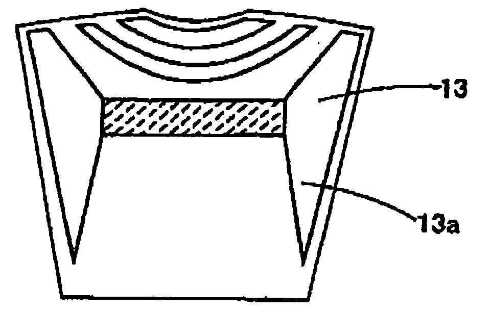
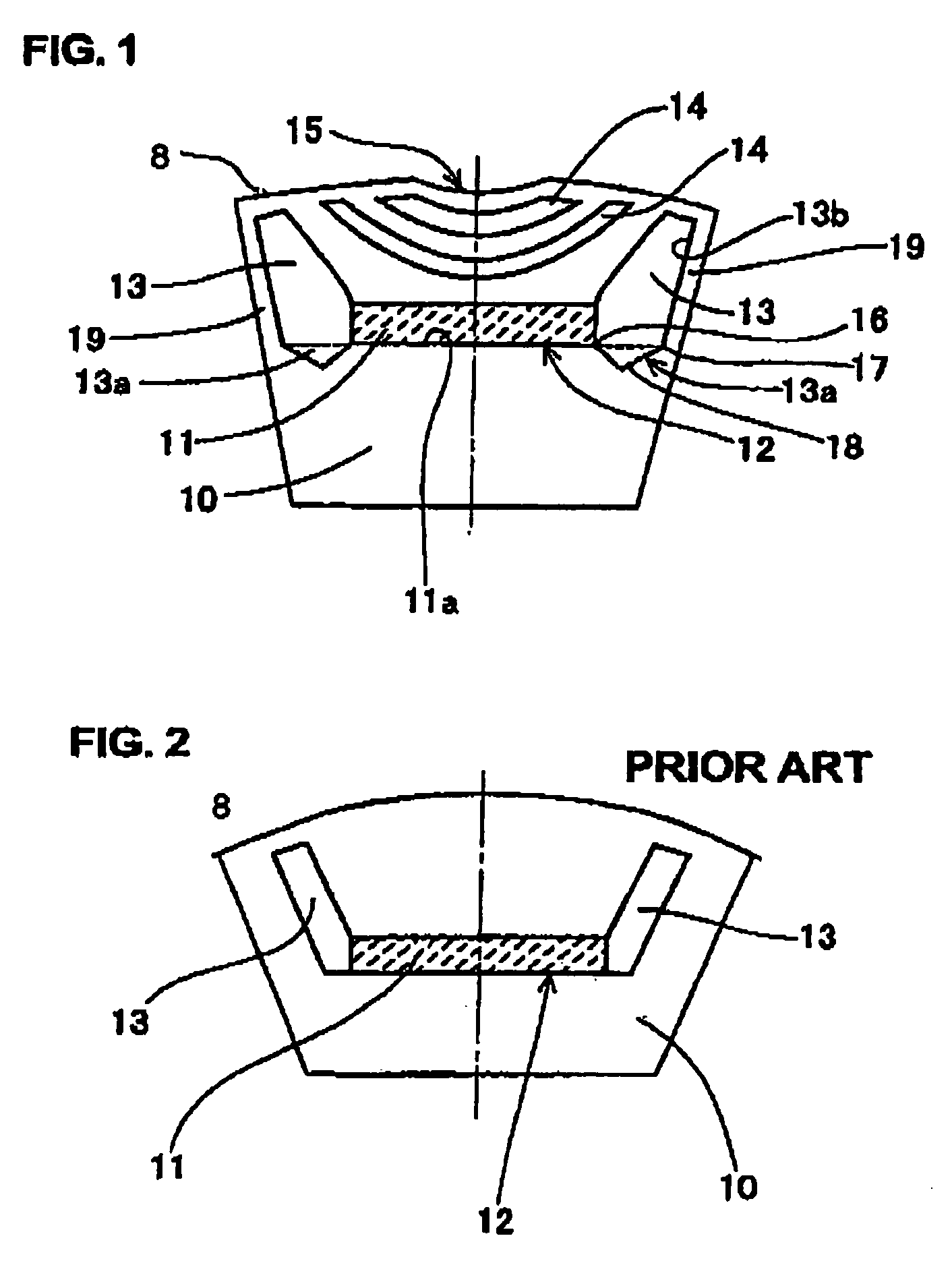
[0048] A first embodiment of a rotor for an IPM rotary electric machine is shown in FIG. 1, which is a partial cross-sectional view perpendicular to the direction of the rotor axis. This shows a portion of the rotor corresponding to one pole pitch, and in particular shows one of a plurality of implanted permanent magnets of the rotor. In FIG. 1, numeral 10 denotes the rotor core, which is formed of stacked laminations of magnetic material, numeral 11 denotes a magnet accommodation cavity having a permanent magnet 12 contained therein, with the magnet accommodation cavity 11 and permanent magnet 12 each being of oblong rectangular shape. Numerals 13 and 23 denote two flux barriers that are located respectively extending circumferentially from opposing sides of the magnet accommodation cavity 11, in the clockwise direction and in the anticlockwise direction respectively. Numerals 14, 24 denote flux barriers, in the form of lens-shaped slits having radially opposed faces that are arc-s...


PUM


Abstract

At each permanent magnet in a rotor of an IPM rotary electric machine, each of a pair of flux barriers respectively disposed adjoining circumferentially opposed side faces of the magnet is formed with a trench portion that extends farther from a circumferential face of the rotor than a position on a corresponding side face that is located farthest, on that side face, from the rotor circumferential face. This prevents part of a flow of magnetic flux, from the stator through the rotor, from being diverted to flow into the magnet. Increased torque or output power is thereby achieved.

Description

[0001] This application is based on and incorporates herein by reference Japanese Patent Application No. 2004-153549 filed on May 24, 2004. BACKGROUND OF INVENTION [0002] 1. Field of Application [0003] The present invention relates to a rotor of an internal permanent magnet (hereinafter abbreviated to IPM) type of rotary electric machine, and in particular to a rotor of an IPM rotary electric machine in which magnetic flux barriers are disposed circumferentially adjacent to each of respective permanent magnets that are implanted within the rotor, for blocking a flow of magnetic flux from each permanent magnet. [0004] 2. Description of Prior Art [0005] IPM rotary electric machines are well known in the prior art, with such a rotary electric machine having a plurality of permanent magnets implanted within the rotor rather than being mounted at the rotor surface. Such a type of rotary electric machine has various advantages over machines in which permanent magnets are mounted at the ro...

Claims


Application Information

Patent Timeline
Patent Type & Authority Applications(United States)
IPC IPC(8): H02K1/27H02K21/12H02K1/22
CPCH02K1/276
Inventor UTAKA, RYOSUKE
Owner DENSO CORP
Why Eureka
Try Eureka