Light source device

a technology of light source and discharge lamp, which is applied in the direction of instruments, lighting and heating apparatus, gas-filled discharge tubes, etc., can solve the problems of unstable emission of discharge lamps, and still exist problems, so as to achieve low wattage operation, suppress discharge lamps, and distinct reduction of wattage

Inactive Publication Date: 2005-12-08
USHIO DENKI KK
View PDF9 Cites 9 Cited by
  • Summary
  • Abstract
  • Description
  • Claims
  • Application Information

AI Technical Summary

Benefits of technology

[0019] In the light source device of the invention, the reflection heating means is used differently, specifically, depending on the high wattage operating mode and the low wattage operating mode. In the high wattage operating mode, the infrared light emitted from the discharge lamp or the UV radiation emitted from the discharge lamp is reflected less than in the low wattage operating mode and preferably is not reflected at all back to the discharge lamp. Therefore, heating of the discharge lamp can be suppressed.
[0020] In the low wattage operating mode, because the infrared light emitted by the discharge lamp or the UV radiation emitted by the discharge lamp is returned to the discharge lamp, the discharge lamp can be subjected to radiant heating. Even when the wattage which is supplied by the power supply device to the discharge lamp is reduced, the mercury can advantageously by vaporized. In this way, low wattage operation with distinctly reduced wattage is enabled. For example, an operating wattage with roughly 50% of the steady-state operating mode can be achieved.
[0021] The invention is further described below with reference to the accompanying drawings.

Problems solved by technology

However, if the mercury density within the arc tube is increased, there are cases in which due to the occurrence of a small temperature change within the arc tube unstable behavior repeatedly occurs, in which the added mercury in the area with a low temperature does not vaporize to some extent and afterwards the unvaporized mercury vaporizes.
The repetition of this unstable behavior makes the emission of the discharge lamp unstable.
In particular, due to the sudden vaporization of the unvaporized mercury, the emission of the discharge lamp instantaneously becomes unstable, by which the so-called flicker phenomenon occurs in a projector device.
Even if the lamp can be built such that the mercury can completely vaporize in the economy mode a problem still would exist.
That is, in the steady-state operating mode, excessive increases in the temperature of the lamp occurs, resulting in the disadvantages of devitrification of the discharge vessel and the like.
Furthermore, if the device can be built such that, by arrangement of a cooling device in which the cooling capacity can be regulated within a wide range (for example, by the arrangement of a cooling fan), in the economy mode, the mercury is caused to completely vaporize and that, in the steady-state operating mode, an excess temperature increase is avoided, the provision of the fan would itself be problematic.
That is, since in a projector device there is a demand for making it smaller (for example, B5 size) and lighter in weight (for example, roughly 1500 g), the provision of such a large cooling device is not practical.
Therefore, even in a projector device provided with an economy mode, in practice, the operating wattage cannot be regulated in a wide range.
The same disadvantage can occur in the case in which the wattage is changed not only in the classification of the steady-state operating mode and the economy mode, but also in the steady-state operating mode.

Method used


Image

  • Light source device
  • Light source device
  • Light source device

Examples


Embodiment Construction

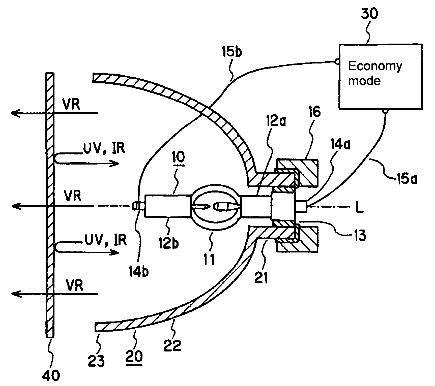
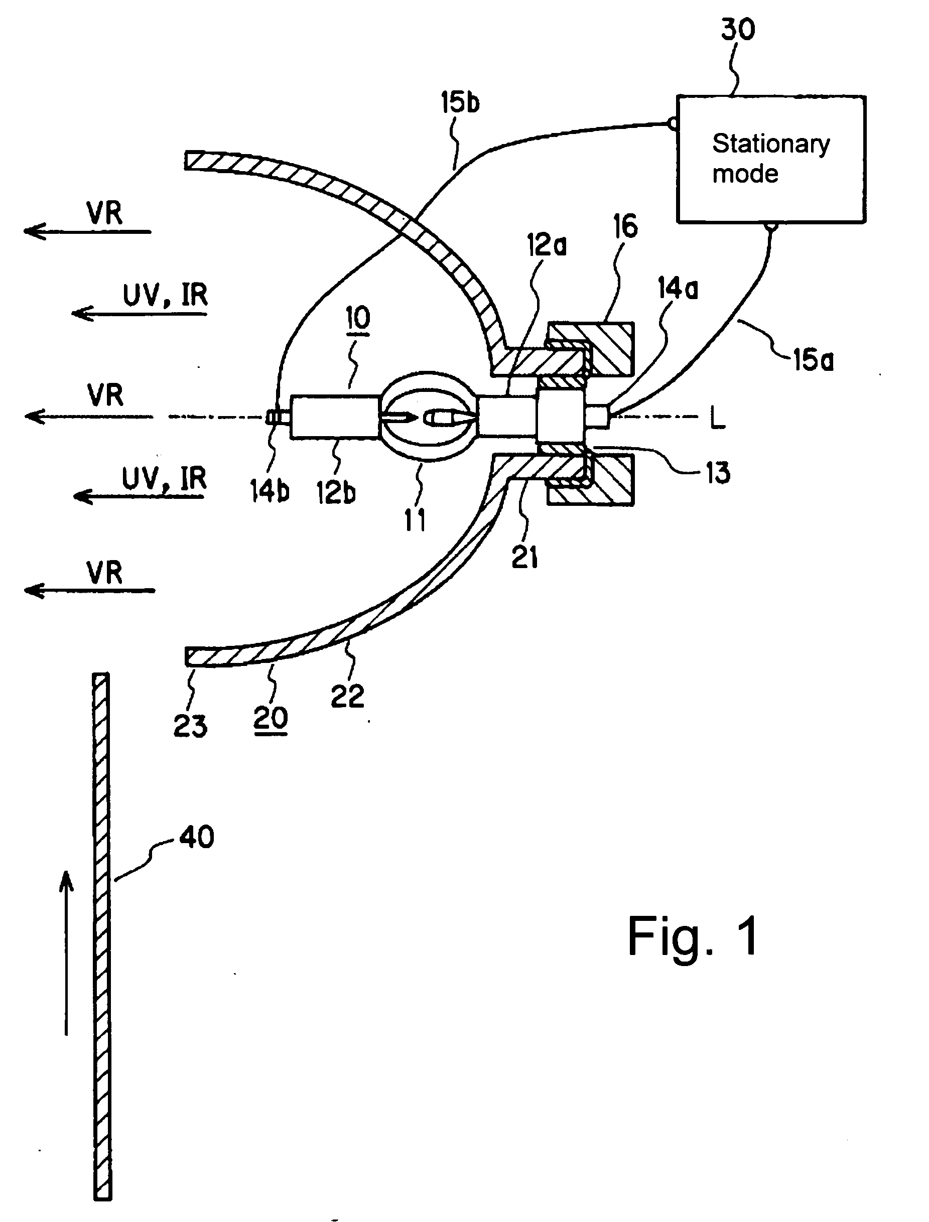
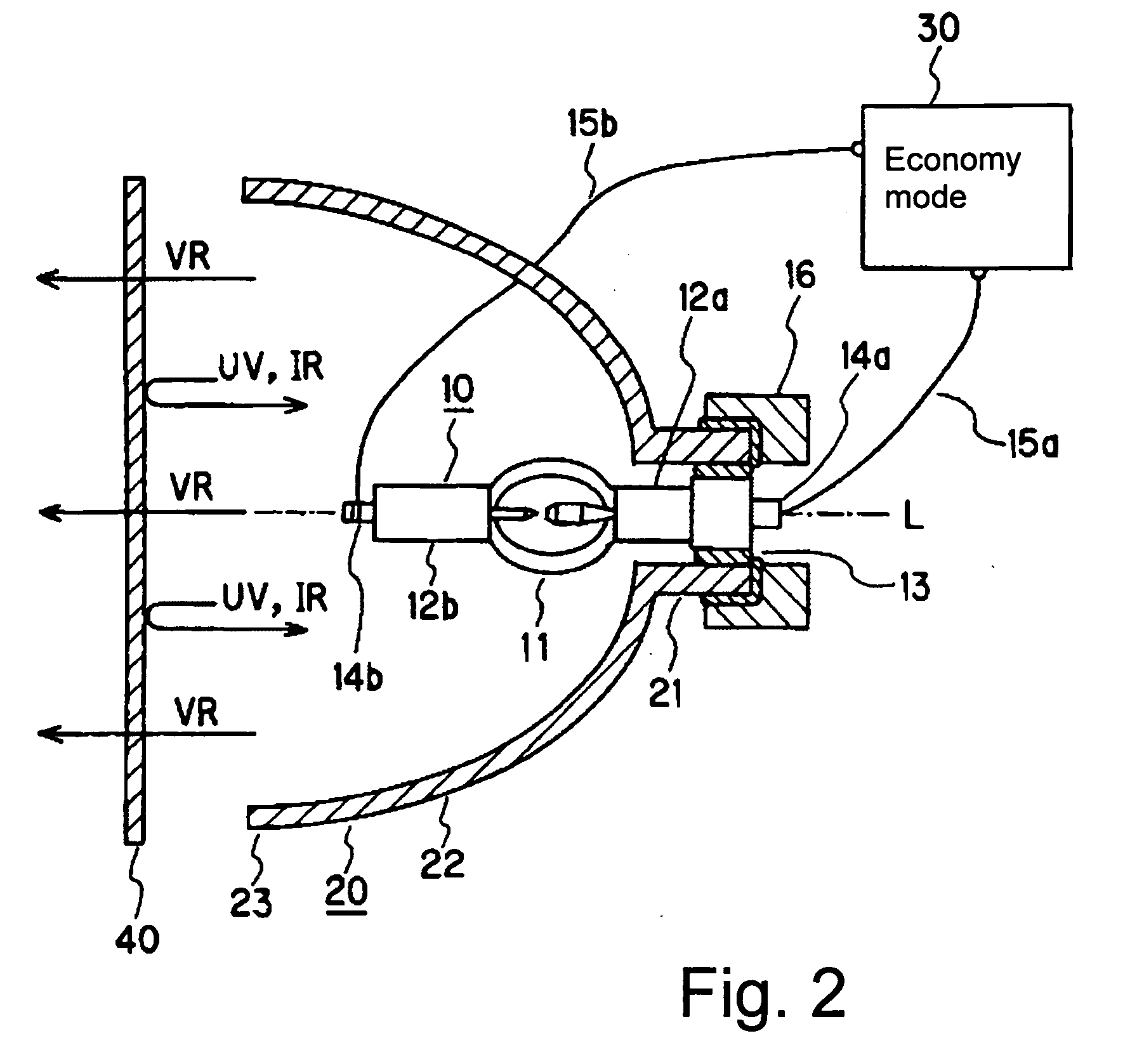
[0034]FIGS. 1 and 2 show a light source device in accordance with a first embodiment of the invention. FIG. 1 shows the arrangement in the high wattage operating mode. FIG. 2 shows the arrangement in the low wattage operating mode. In the embodiments described below, a steady-state operating mode is described as a specific example of the high wattage operating mode and the economy mode is described as a specific example of the low wattage operating mode.

[0035] The light source device comprises a discharge lamp 10, a concave reflector 20 which surrounds the discharge lamp 10, a power supply device 30 which supplies power to the discharge lamp 10, and a reflection heating means 40.

[0036] The two drawings differ from one another only by the positions of the reflection heating means 40. The arrangements of the discharge lamp 10 and of the concave reflector 20 are basically identical in the two drawings.

[0037] The discharge lamp 10 is a so-called ultra-high pressure mercury lamp of th...


PUM

PropertyMeasurementUnit
weightaaaaaaaaaa
wavelengthsaaaaaaaaaa

Abstract

A light source device for a projector device having a discharge lamp with a silica glass discharge vessel containing a pair of opposed electrodes and at least 0.15 mg/mm3 of mercury, a concave reflector which surrounds the discharge lamp and reflects light emitted from the discharge lamp in a given direction, and a power supply device which selectively supplies a first wattage and a lower second wattage, is provided with a reflection heating arrangement which, in operation of the discharge lamp with the lower second wattage, returns at least part of the light emitted by the discharge lamp in the direction of the discharge lamp, and in operation of the discharge lamp at the first, higher wattage returns less light than in operation with the second wattage in the direction of the discharge lamp.

Description

BACKGROUND OF THE INVENTION [0001] 1. Field of the Invention [0002] The invention relates to a light source device, especially to a light source device which is used for the optical system of a projector device using liquid crystals and a DMD device (D(igital) M(icro mirror) D(evice)). [0003] 2. Description of the Prior Art [0004] Recently, there has been a great demand for prolonging the service life of a projector device and making it smaller. There is also a demand for increasing the radiance of the discharge lamp as the light source. As the light source, a discharge lamp is suggested in which, by an increased mercury vapor pressure, the broadening of the arc is suppressed (the arc is compressed) and a distinct increase of radiance is enabled. This discharge lamp is disclosed, for example, in JP-A-2-148561 (corresponding to U.S. Pat. No. 5,109,181) and JP-A-6-52830 (corresponding to U.S. Pat. No. 5,497,049). [0005] However, if the mercury density within the arc tube is increased,...

Claims


Application Information

Patent Timeline
Patent Type & Authority Applications(United States)
IPC IPC(8): G03B21/14F21S2/00F21V5/00F21V7/22F21V9/04F21V9/06F21V14/08F21V29/00F21Y101/00G03B21/20H01J5/16H01J61/00H01J61/04H01J61/20H01J61/40H01J61/52H01J61/82H01J61/86
CPCF21V9/04F21V9/06F21V14/08G03B21/2026H01J61/86G03B21/2053G03B21/2066H01J61/045F21V7/24F21V7/28
Inventor KOBAYASHI, YUICHIYAMASHITA, TAKASHI
Owner USHIO DENKI KK
Why Eureka
Try Eureka