Electrical protection device & method for a communication circuit

a communication circuit and protection device technology, applied in the direction of electrical equipment, circuit arrangements, instruments, etc., can solve the problems of disruption of communication circuit and communication service provided by the communication facility, unable to identify the source of the outage, and the components of the semiconductor-based telecommunication equipment susceptible to excessive voltag

Inactive Publication Date: 2005-12-08
ASCO POWER TECH LP
View PDF32 Cites 12 Cited by
  • Summary
  • Abstract
  • Description
  • Claims
  • Application Information

AI Technical Summary

Problems solved by technology

Semiconductor based components of telecommunication equipment are susceptible to excessive voltage including transient over voltages that last only a few microseconds.
In such a case, the telecommunication equipment and / or the communication user may determine that the communication has ceased to operate, however, neither the user or the telecommunication service provider can identify the source of the outage as being an open circuit or fuse within the protection device.
When the surge suppression device sacrifices itself, the device generally disconnects the incoming line from the equipment line which results in a disruption of the communication circuit and service provided by the communication facility.
However, visual indicators require a person such as a technician visually inspect the visual indicators which helps in repair and maintenance of the facility, but does not help in remotely identifying the source and location of the problem.
However, the communication signal is sensitive to energy drains and may in fact cease working due solely to the energy requirements of the visual indicator.
As such, visual indicators are not typically provided in protective devices.

Method used


Image

  • Electrical protection device & method for a communication circuit
  • Electrical protection device & method for a communication circuit
  • Electrical protection device & method for a communication circuit

Examples


Embodiment Construction

[0021] The following description is merely exemplary in nature and is not intended to limit the invention, its application, or uses.

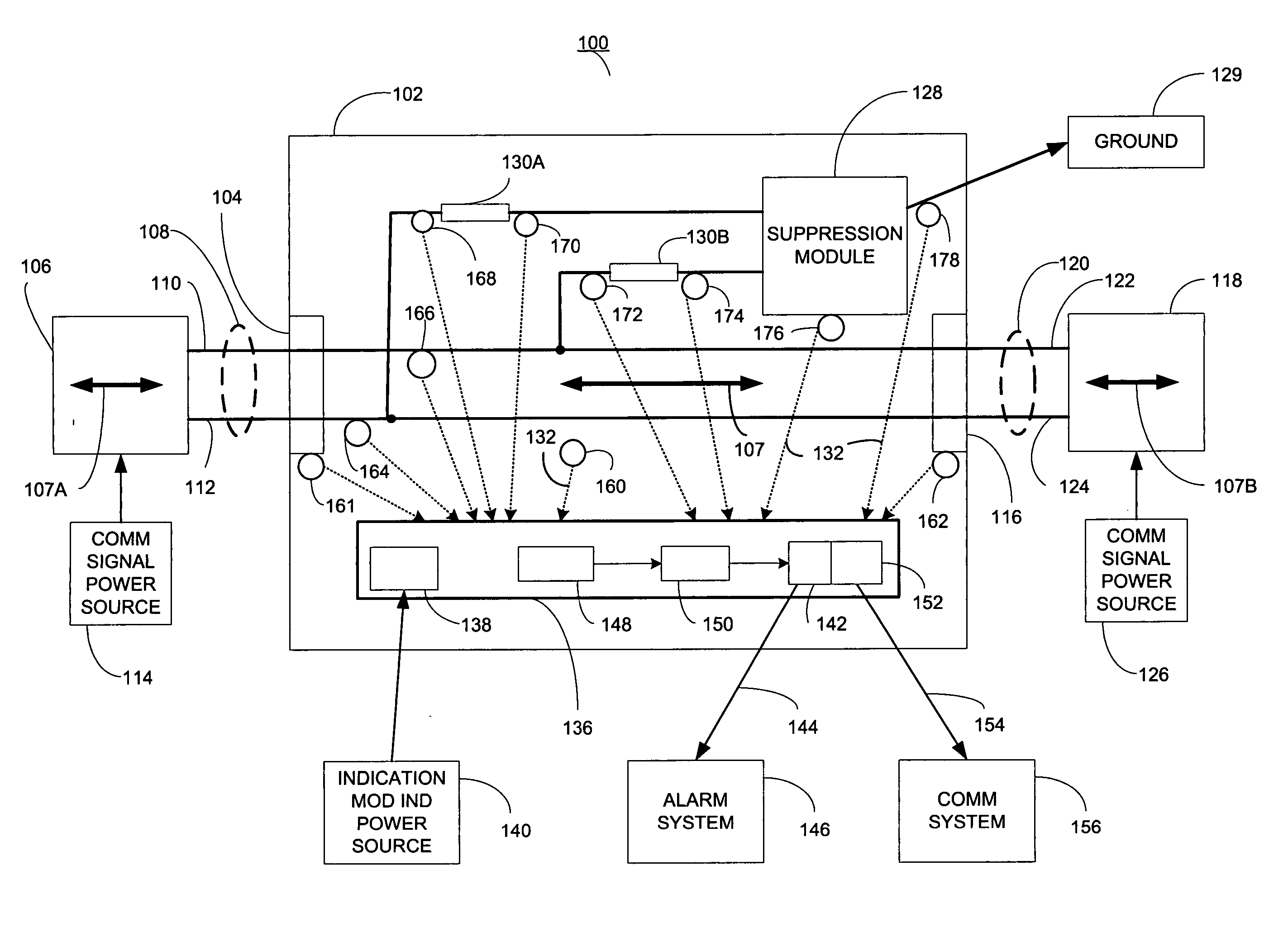
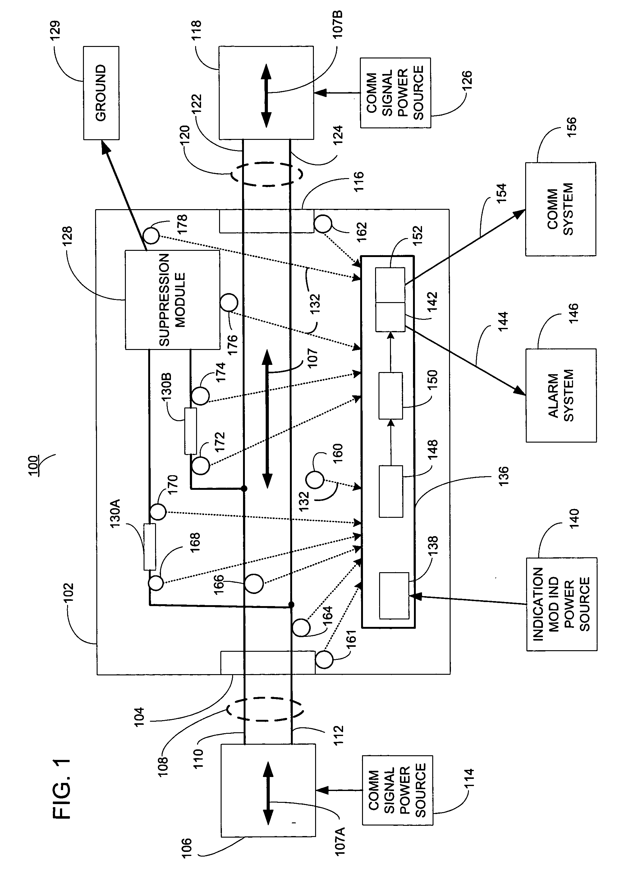
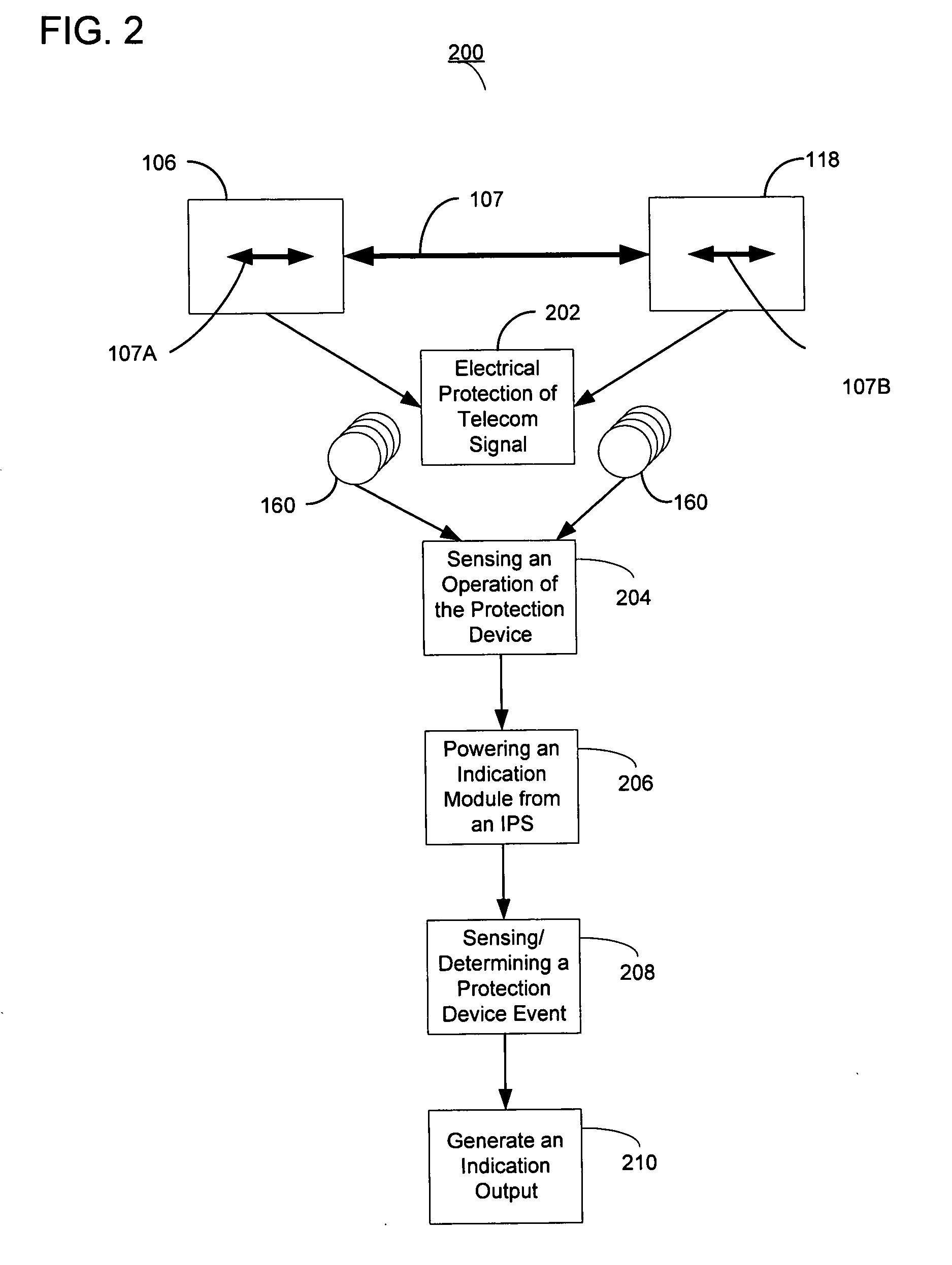
[0022] In one embodiment, the invention is a protection device for a telecommunication circuit. The protection device has an input interface for coupling to an input communication medium and an output interface for coupling to an output communication medium. The input interface and output interface are coupled to transfer a telecommunication signal between the input communication medium and the output communication medium. The device also has a suppression module coupled to the input interface and the output interface to provide a transfer limit between the input interface and the output interface. The protection device includes one or more sensors monitoring one or more protection device parameters. The device also includes an indication module coupled to the sensor. The indication module receives power from an indication power source that is separate...


PUM


Abstract

A protection device for a communication circuit that includes a sensor monitoring a protection device parameter and an indication module coupled to the sensor. The indication module generates an indication output as a function of the protection device parameter indicating a protection device event. The indication module receives power from an indication power source separate from the telecommunication signal. Also a method for protecting a telecommunication signal with a protection device including sensing a protection device parameter indicating a protection device event. The method also includes powering an indication module from an indication power source that is separate from the telecommunication signal. The method further includes generating an indication output from the indication module as a function of the protection device parameter indicating the protection device event.

Description

FIELD OF THE INVENTION [0001] The present invention relates to a protection device for use in telecommunication systems and more specifically to a high speed data line surge suppression device having a failure indication output. BACKGROUND OF THE INVENTION [0002] In telecommunication systems, protection devices are employed to protect equipment from the effects of lightning or other high voltage surges and unwanted voltages of lower magnitude. A protector device is placed in a connection between a telephone exchange line of the local telecommunication provider and telecommunication equipment often at a customer location. The protection device protects the equipment connected to the exchange line from extraneous power sources and surges. [0003] The protection device includes an input transmit and receive connection with the exchange facility and an output transmit and receive connection with the protected equipment. The protection device includes a mechanism for automatically disconn...

Claims


Application Information

Patent Timeline
Patent Type & Authority Applications(United States)
IPC IPC(8): G08B21/00G08B21/20
CPCG08B21/185
Inventor MCDONALD, JAMES N. JR.BENTLEY, GREGORY L.
Owner ASCO POWER TECH LP
Why Eureka
Try Eureka