Optically-augmented microwave imaging system and method

a microwave imaging and optical technology, applied in the field of optically augmented microwave imaging system and method, can solve the problems of poor resolution or processing artifacts, often computationally intensive construction process, etc., and achieve the effects of improving resolution, reducing the computational complexity of constructing the microwave image, and fast and simple algorithms

Active Publication Date: 2005-12-08
AGILENT TECH INC
View PDF22 Cites 26 Cited by
  • Summary
  • Abstract
  • Description
  • Claims
  • Application Information

AI Technical Summary

Benefits of technology

[0006] The optical imaging system uses a fast and simple algorithms to extract the optical image information. The optical image information can reduce the computational complexity of constructing the microwave image and limit the microwave illumination to the regions of interest on the object, thereby enabling improved resolution and a reduction in artifacts of the microwave image. Furthermore, the invention provides embodiments with other features and advantages in addition to or in lieu of those discussed above. Many of these features and advantages are apparent from the description below with reference to the following drawings.

Problems solved by technology

However, the construction process is often computationally intensive.
In addition, in many instances, the resulting constructed image suffers from poor resolution or processing artifacts, such as speckles.

Method used


Image

  • Optically-augmented microwave imaging system and method
  • Optically-augmented microwave imaging system and method
  • Optically-augmented microwave imaging system and method

Examples


Embodiment Construction

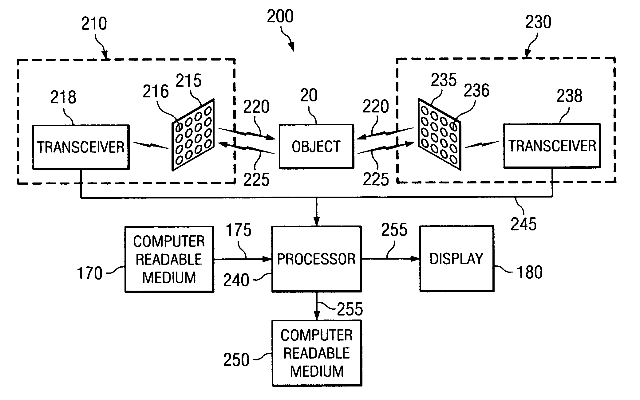
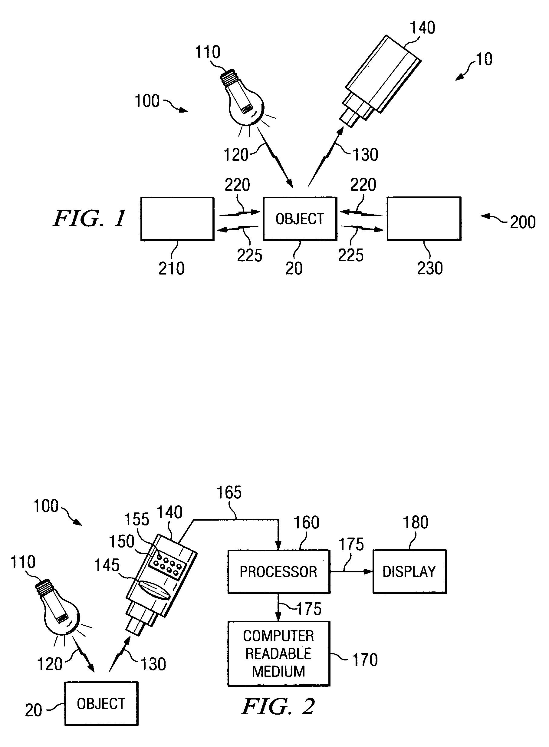
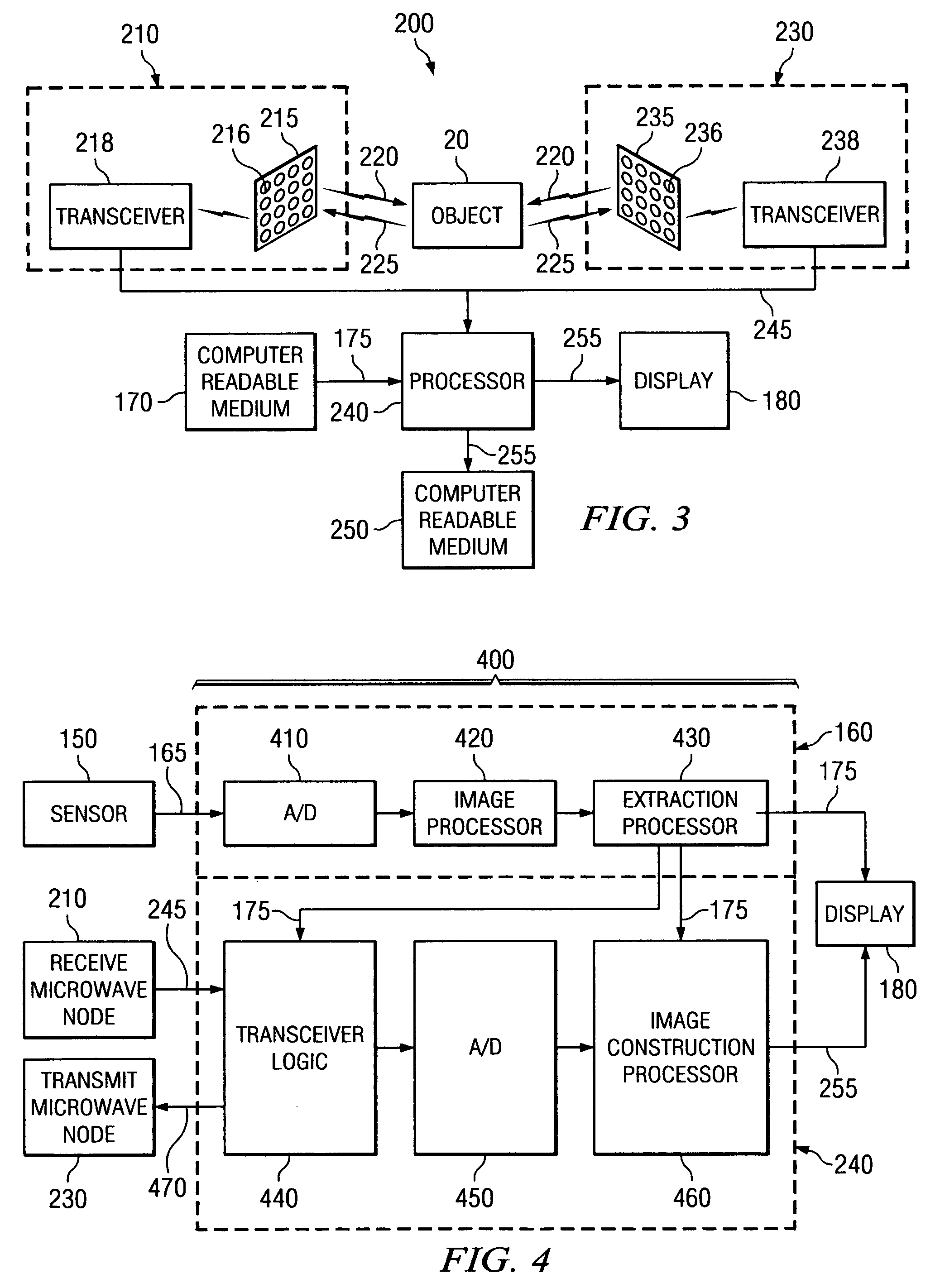
[0021]FIG. 1 is a simplified representation of an exemplary imaging system 10 in which a microwave imaging system 200 is augmented with an optical imaging system 100. As used herein, the term “microwave imaging system” refers to an imaging system operating the microwave frequency range, and the resulting images obtained by the microwave imaging system are referred to as “microwave images.” In addition, as used herein, the term “optical imaging system” refers to an imaging system operating in the visible light or near IR frequency range, and the resulting images obtained by the optical imaging system are referred to as “optical images” in order to differentiate these images from microwave images obtained by the microwave imaging system.

[0022] The imaging system 10 can be used, for example, in airport security systems for inspecting luggage or passengers, or any other microwave imaging application. The optical imaging system 100 includes a light source 110 for illuminating an object ...


PUM

PropertyMeasurementUnit
wavelengthsaaaaaaaaaa
frequencyaaaaaaaaaa
wavelengthsaaaaaaaaaa

Abstract

An imaging system includes an optical (visible-light or near IR) imaging system and a microwave imaging system. The optical imaging system captures an optical image of the object, produces optical image data representing the optical image and extracts optical image information from the optical image data. The microwave imaging system produces microwave image data representing a microwave image of the object in response to the optical image information.

Description

BACKGROUND OF THE INVENTION [0001] A typical microwave imaging system operates in the frequency range of 1 GHz to 100 GHz, corresponding to wavelengths in free-space of 30 cm to 0.33 cm. By comparison, optical or visible light imaging systems operate in the frequency range of 750 THz to 430 THz, corresponding to wavelengths of 0.4 μm to 0.7 μm. Though both are electromagnetic waves in nature, the different wavelengths produce different imaging characteristics. For example, microwave radiation is capable of penetrating objects that are opaque to visible light. As a result, microwave imaging systems are able to obtain measurements of the object beyond the external layer. [0002] Traditional microwave imaging systems rely on measuring the microwave radiation from an object, and constructing an image of the object based on the radiation measurements. The radiation measurement is obtained using an antenna and adjacent receiver circuitry. The antenna can be a single element antenna, or one...

Claims


Application Information

Patent Timeline
Patent Type & Authority Applications(United States)
IPC IPC(8): G01N22/00G01S13/89G01S13/86G01S17/88
CPCG01N22/00G01S13/867G01S13/89
Inventor BAHARAV, IZHAKTABER, ROBERT C.ROSNER, S. JEFFREY
Owner AGILENT TECH INC
Why Eureka
Try Eureka