Fast Log-Likelihood Ratio (LLR) Computation for Decoding High-Order and High-Dimensional Modulation Schemes

a high-order and high-dimensional modulation scheme technology, applied in the field of digital communication, can solve the problems of high power consumption, complex computation of llrs, and degradation of signal with noise, and achieve the effect of reducing the number of calculations, reducing the computational complexity of nonlinear filters, and more accurate llr approximation

Active Publication Date: 2017-05-04
MITSUBISHI ELECTRIC RES LAB INC
View PDF0 Cites 27 Cited by
  • Summary
  • Abstract
  • Description
  • Claims
  • Application Information

AI Technical Summary

Benefits of technology

[0010]Specifically, some embodiments are based on recognition that the LLRs of all codewords can be calculated to determine the most likely codeword. However, the LLR can also be approximated by using the relative likelihood of the codewords with respect to another codeword. In addition, some embodiments are based on a realization that by considering only nearest neighbor codewords an almost exact LLR can be approximated while significantly reducing the number of calculations. For example, in one embodiment of the invention for 24D extended Golay code, the number of calculations for determining the LLRs of modulated symbols is reduced from 4096 to 759 by considering the likelihoods of only nearest neighbors.
[0011]In some embodiments of the invention, the LLR approximation is based on belief propagation over factor graph for block-coded high-dimensional modulations, which can be expressed by a parity-check matrix. The output of LLR values from the belief propagation can be further refined by a nonlinear filter, including artificial neural networks and Volterra fil

Problems solved by technology

The communication channel distorts the transmitted signal with a channel response and further degrades the signal with noise and interference.
The computation for the LLRs can be complex, leading to high power consumption.
The computational difficulty for LLRs calculation is even more apparent for optical communica

Method used


Image

  • Fast Log-Likelihood Ratio (LLR) Computation for Decoding High-Order and High-Dimensional Modulation Schemes
  • Fast Log-Likelihood Ratio (LLR) Computation for Decoding High-Order and High-Dimensional Modulation Schemes
  • Fast Log-Likelihood Ratio (LLR) Computation for Decoding High-Order and High-Dimensional Modulation Schemes

Examples


Embodiment Construction

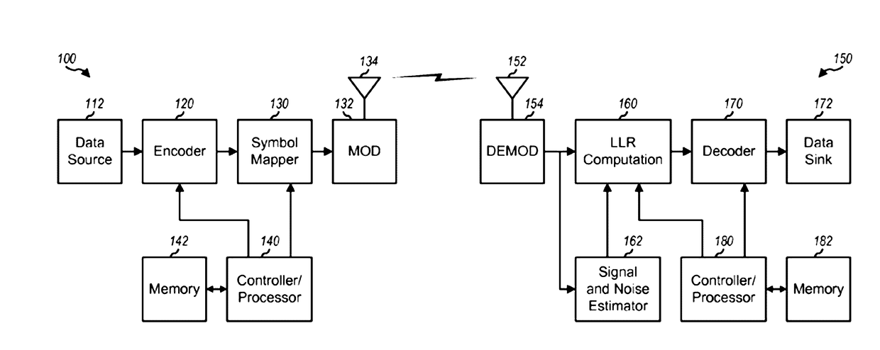
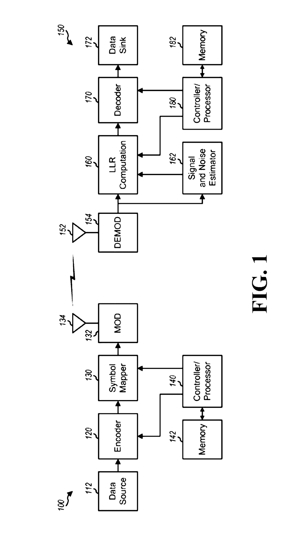
[0025]FIG. 1 shows a block diagram of a design of a transmitter 100 and a receiver150 in a digital communication system. At transmitter 100, an encoder 120 receives a block of data from a data source 112, encodes the data block based on an FEC coding scheme, and provides code bits. A data block can also be referred to as a transport block, a packet, or a frame. An encoder 120 can perform rate matching and delete or repeat some or all of the code bits to obtain a desired number of code bits for the data block. The encoder 120 can also perform channel interleaving and reorder the code bits based on an interleaving scheme. A symbol mapper 130 maps the code bits to modulation symbols based on a modulation scheme, which may be QPSK, QAM, etc. A modulator (MOD) 132 can perform processing for code-division multiplexing (CDM), frequency-division multiplexing (FDM), orthogonal frequency-division multiplexing (OFDM), single-carrier FDM (SC-FDM), or single-carrier (SC). The modulator 132 then ...


PUM


Abstract

A method receives the symbol transmitted over a channel, selects, from a constellation of codewords, a first codeword neighboring the received symbol and a set of second codewords neighboring the first codeword, and determines a relative likelihood of each second codeword being the transmitted symbol with respect to a likelihood of the first codeword being the transmitted symbol. Next, the method determines an approximation of a log-likelihood ratio (LLR) of each data bit in the received symbol as a log of a ratio of a sum of the relative likelihoods of at least some of the second codewords having the same value of the data bit to a sum of the relative likelihoods of at least some of the second codewords having different value of the data bit and decodes the received symbol using the LLR of each data bit.

Description

FIELD OF THE INVENTION[0001]The present invention relates generally to digital communications, and more specifically to computing log-likelihood ratio (LLRs) for decoding modulated symbols.BACKGROUND OF THE INVENTION[0002]In a digital communication system, a transmitter typically encodes traffic data based on a forward-error correction (FEC) coding scheme to obtain code bits and further maps the code bits to modulation symbols based on a modulation scheme. The transmitter then processes the modulation symbols to generate a modulated signal and transmits this signal via a communication channel. The communication channel distorts the transmitted signal with a channel response and further degrades the signal with noise and interference.[0003]A receiver receives the transmitted signal and processes the received signal to obtain symbols, which can be distorted and noisy versions of the modulation symbols sent by the transmitter. The receiver can then compute log-likelihood ratio (LLRs) f...

Claims


Application Information

Patent Timeline
IPC IPC(8): H04L1/00
CPCH04L1/0045H04L1/0061H04L1/0057H04L1/0042H04L25/067H04L27/38
Inventor MILLAR, DAVIDKOIKE-AKINO, TOSHIAKIKOJIMA, KEISUKEPARSONS, KIERAN
Owner MITSUBISHI ELECTRIC RES LAB INC
Why Eureka
Try Eureka