
Transform Domain Fast Mode Search for Spatial Prediction in Advanced Video Coding

Active Publication Date: 2008-12-11
TEXAS INSTR INC
View PDF6 Cites 30 Cited by
  • Summary
  • Abstract
  • Description
  • Claims
  • Application Information

AI Technical Summary

Benefits of technology

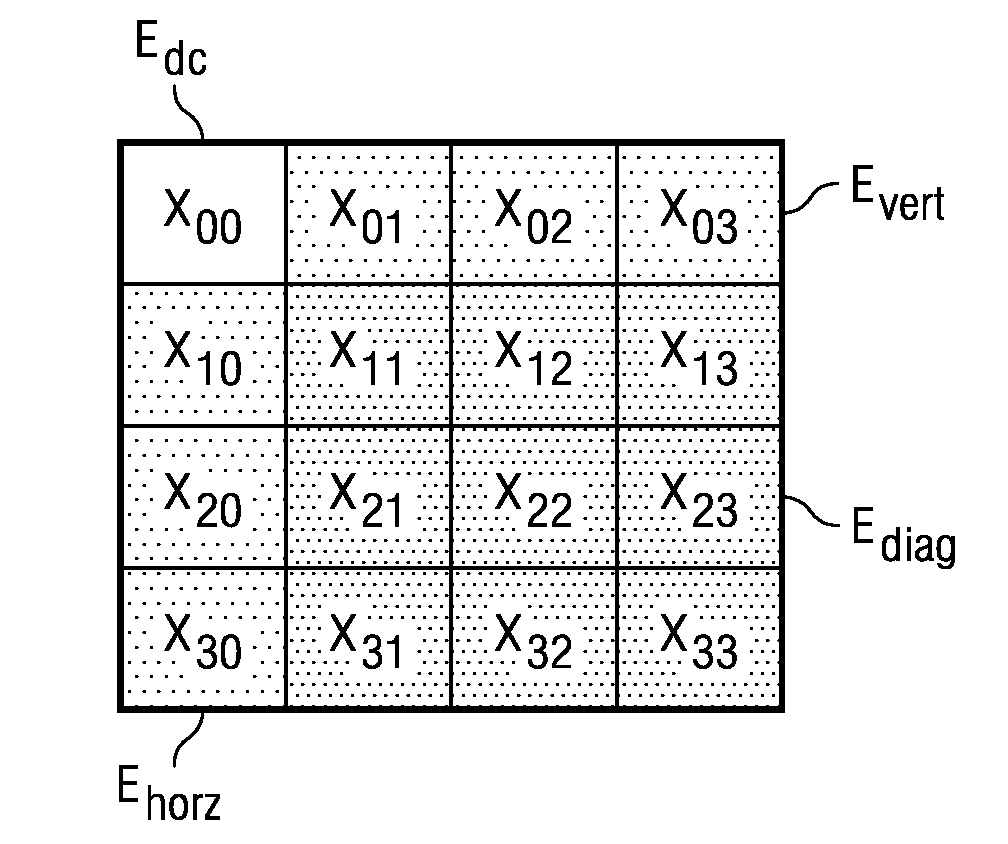
[0005]To reduce the computational complexity of video coding in I4×4 mode, this invention uses an algorithm based on transform domain energy distribution of input samples. Experiments suggest that features derived from transform domain energy of the input samples can be used to classify a 4×4 block on the basis of direction which can be used for pruning certain modes. This algorithm first looks at energy distribution among transform domain coefficients and classifies each 4×4 block into one of the five classes. These five classes are DC, horizontal, vertical, diagonal and ambiguous. Each class contains a small sub-set of Intra 4×4 prediction modes associated with the specific direction. For example, the horizontal class contains horizontal, horizontal-up and horizontal-down prediction modes. Following determination of the class, a second step conducts a full search amongst the small set of modes within the class. The first step reduces computational complexity tremendously while the second step helps obtain the best possible compression efficiency at the least possible computational cost.
[0007]This invention reduces the complexity of I4×4 mode decisions by around 70% while maintaining almost same quality as compared to a brute force algorithm. This invention uses the same integer discrete cosine transform as used in forward encoding path for which faster implementation is available. This reduces additional complexity of transforming input samples.

Problems solved by technology

The I4×4 mode is more demanding in computational complexity.
The complexity of determining the optimal I4×4 prediction mode is challenging because: (i) there are nine allowed modes that must be searched; and (ii) the I4×4 mode decision depends on the reconstructed pixels of other causal 4×4 blocks within the same macroblock.
The optimal manner of determining the prediction mode is extremely complex and not suitable for real-time systems.

Method used


Image

  • Transform Domain Fast Mode Search for Spatial Prediction in Advanced Video Coding
  • Transform Domain Fast Mode Search for Spatial Prediction in Advanced Video Coding
  • Transform Domain Fast Mode Search for Spatial Prediction in Advanced Video Coding

Examples


Embodiment Construction

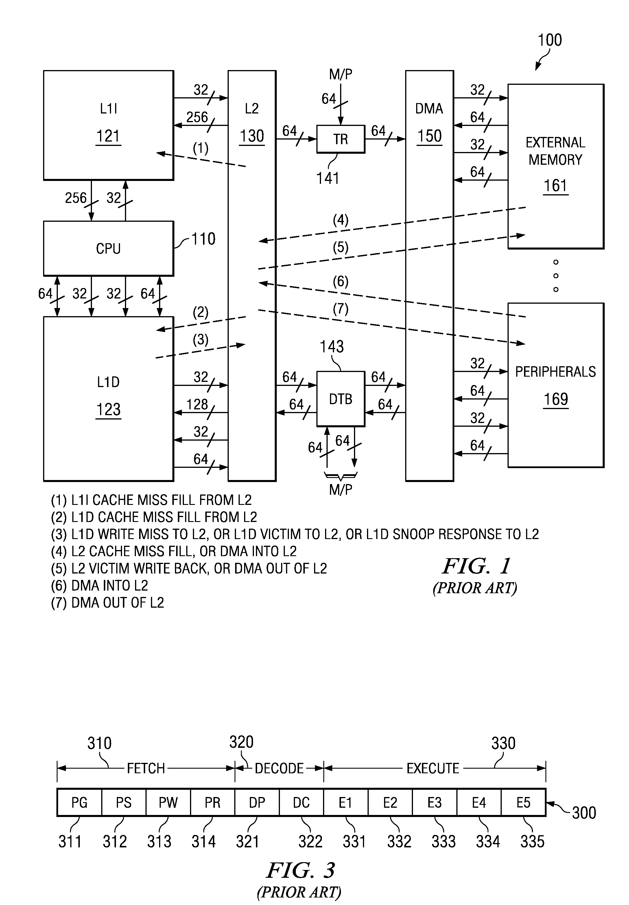
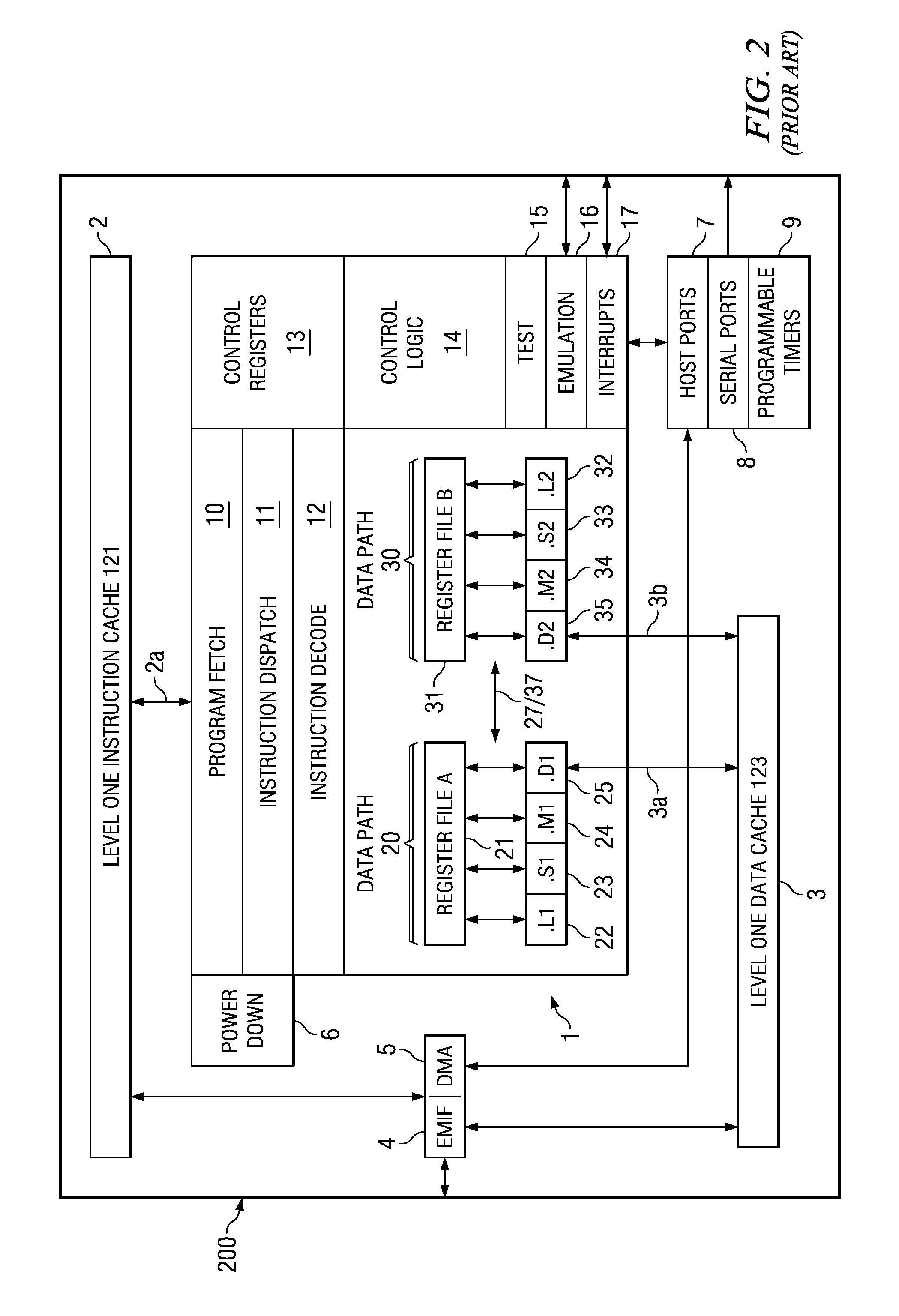
[0020]FIG. 1 illustrates the organization of a typical digital signal processor system 100 to which this invention is applicable (prior art). Digital signal processor system 100 includes central processing unit core 110. Central processing unit core 110 includes the data processing portion of digital signal processor system 100. Central processing unit core 110 could be constructed as known in the art and would typically includes a register file, an integer arithmetic logic unit, an integer multiplier and program flow control units. An example of an appropriate central processing unit core is described below in conjunction with FIGS. 2 to 4.

[0021]Digital signal processor system 100 includes a number of cache memories. FIG. 1 illustrates a pair of first level caches. Level one instruction cache (L1I) 121 stores instructions used by central processing unit core 110. Central processing unit core 110 first attempts to access any instruction from level one instruction cache 121. Level on...


PUM


Abstract

This invention is method for determining direction mode for an image block in intra prediction of video frames. The method calculates a plurality of energy terms from the spatial frequency domain image block, then determines a coarse classification from these energy terms. For at least some coarse classifications the method searches from among a subset of less than all possible direction modes. The method also searches a most likely direction mode determined from neighbor blocks when available.

Description

CLAIM OF PRIORITY[0001]This application claims priority under 35 U.S.C. 119(e)(1) to U.S. Provisional Application No. 60 / 943,080 filed Jun. 11, 2007.TECHNICAL FIELD OF THE INVENTION[0002]The technical field of this invention is video data encoding.BACKGROUND OF THE INVENTION[0003]Spatial Domain Intra prediction is one of the important tools in the advanced video coding standards such as H.264, VC1 and AVS. H.264 intra prediction allows two modes, an Intra 16×16 (I16×16) mode and an Intra 4×4 (I4×4) mode based on the prediction block size. Experiments reveal that the I16×16 mode works well in flat regions of the image. In contrast, the I4×4 mode is especially effective at lower resolutions (such as QVGA, CIF, QCIF etc) or when the picture has more detail. The I4×4 mode is more demanding in computational complexity. The complexity of determining the optimal I4×4 prediction mode is challenging because: (i) there are nine allowed modes that must be searched; and (ii) the I4×4 mode decis...

Claims


Application Information

Patent Timeline
IPC IPC(8): G06K9/36
CPCH04N19/176H04N19/147H04N19/61H04N19/42H04N19/14H04N19/48H04N19/11
Inventor NAGORI, SOYEB N.
Owner TEXAS INSTR INC
Learn More