
Parallax scanning through scene object position manipulation

a scene object and position manipulation technology, applied in the field of visual arts, can solve the problems of large amount of computation, heavy processing resource burden, and nevertheless two-dimensionality

Active Publication Date: 2005-12-08
VISION III IMAGING
View PDF5 Cites 17 Cited by
  • Summary
  • Abstract
  • Description
  • Claims
  • Application Information

AI Technical Summary

Problems solved by technology

Although these images can be rendered with incredible results, they are nevertheless two-dimensional because they lack the parallax depth information found in true three dimensional images.
Using this ray-tracing method to simulate optical effects such as depth of field variations, however, may require large amounts of computation and can place a heavy burden on processing resources.
Therefore, such a ray tracing method may be impractical for certain applications, such as 3D computer games, animation, and other graphics applications, which require quick response.
This property, however, may cause instability in the displayed parallax images.
Because objects far from the point of view contribute less depth information than objects closer to the point of view, the motion of distant objects is less important and may even cause image instability (e.g., a jitter effect caused by the motion of objects between successive parallax image frames).
Using the method of the '347 patent (i.e., moving a virtual point of view to generate parallax information), under certain circumstances, direct control of object stability at depth extremes may be impractical.

Method used


Image

  • Parallax scanning through scene object position manipulation
  • Parallax scanning through scene object position manipulation
  • Parallax scanning through scene object position manipulation

Examples


Embodiment Construction

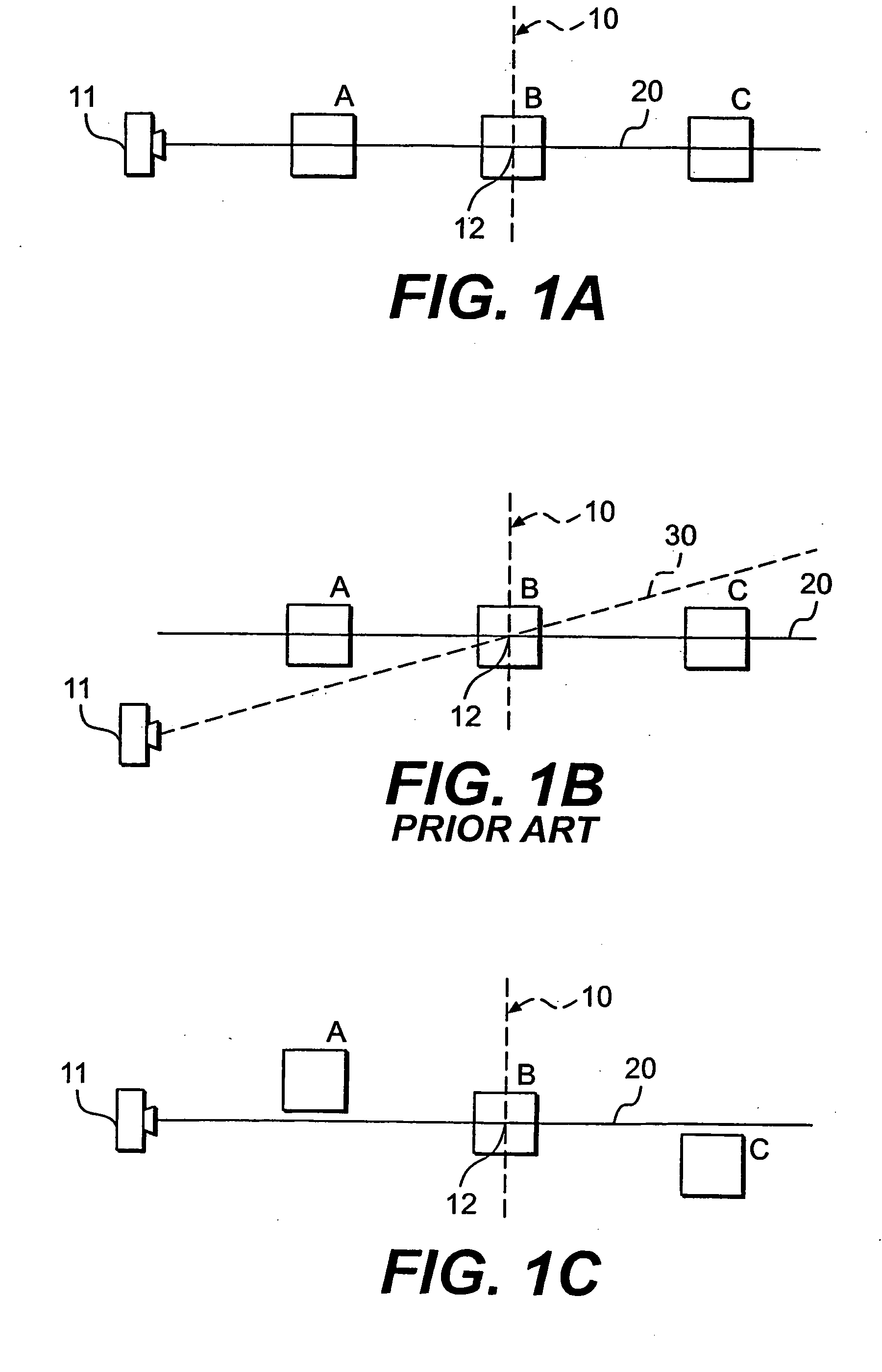
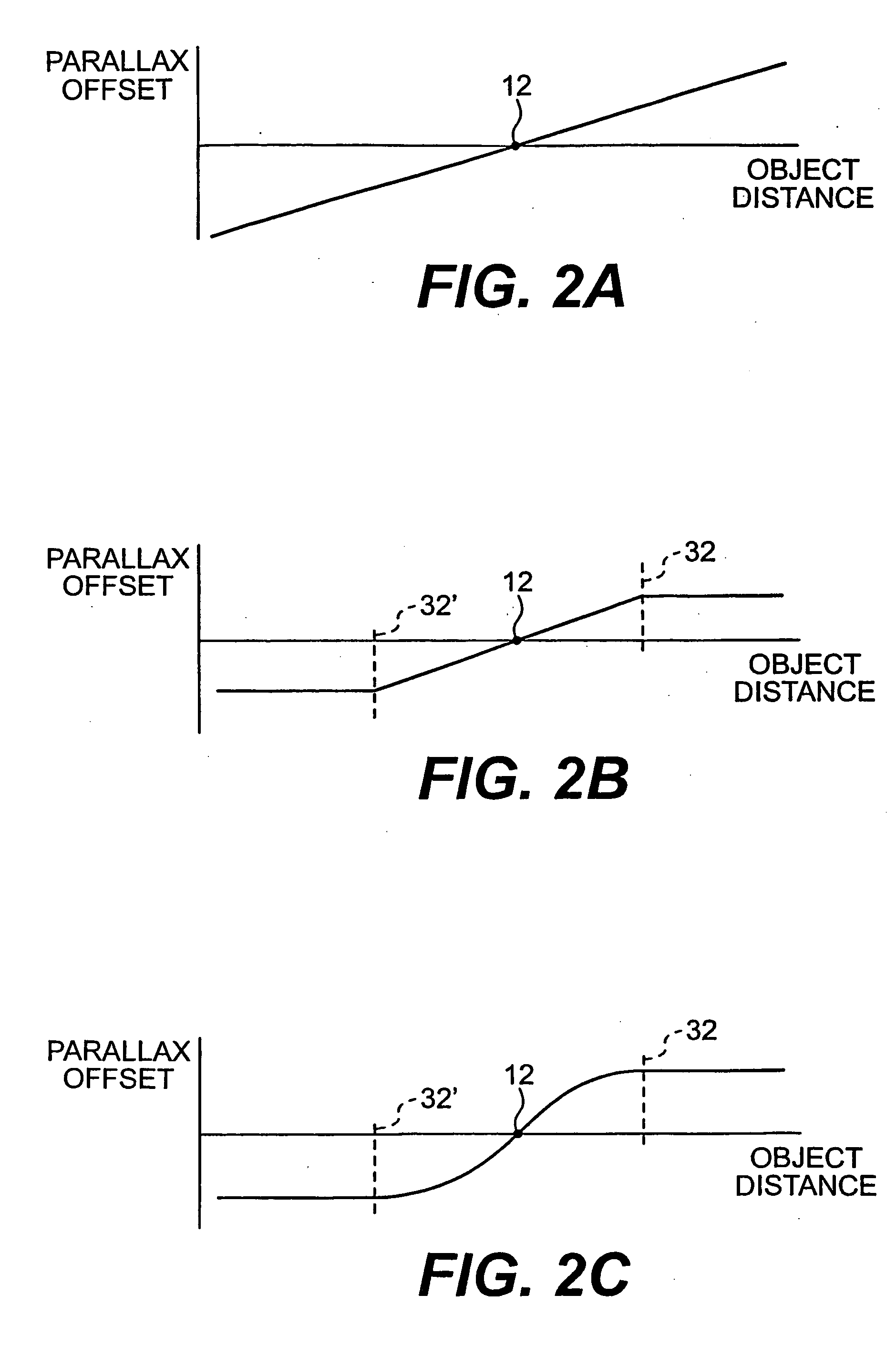
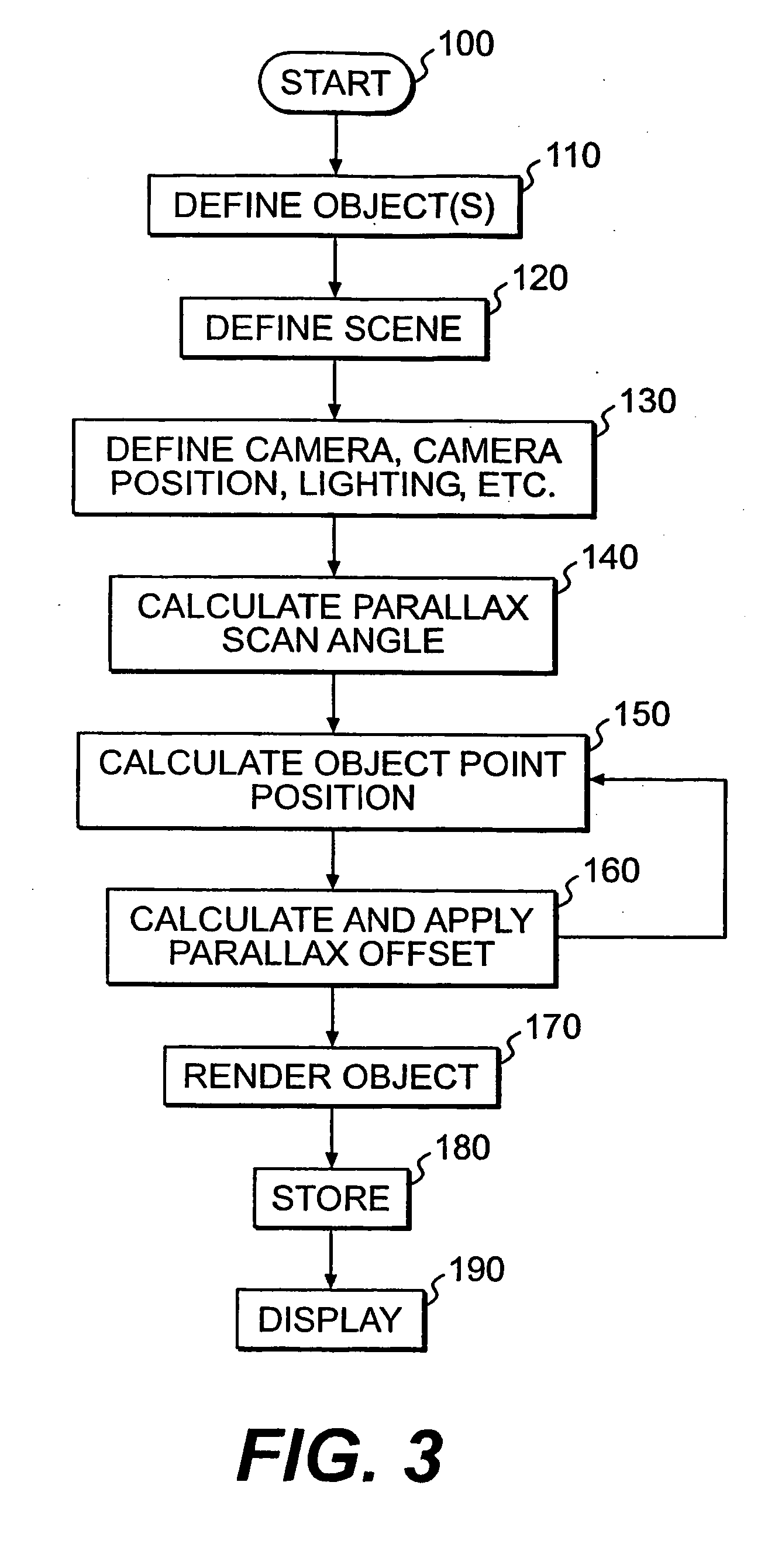
[0024] The present invention includes a system and method for using parallax scanning to generate and display autostereoscopic 3D computer graphics images. That is, by incorporating parallax information into computer graphics images, these images may be perceived as having three dimensional characteristics. The invention improves on the prior art methods in at least two ways. First, automatic scan control algorithms calculate the proper parallax scan parameters based on the 3D virtual scene information. Second, instead of applying parallax scanning to a 3D virtual scene by moving a camera and holding scene geometry fixed, the method of the present invention applies parallax scanning to the scene by holding the camera fixed and moving the scene objects.

[0025] Previous parallax scanning methods as applied to computer imaging incorporated parallax information into scene images by moving the iris of the camera with respect to the scene objects being imaged. The present invention revers...


PUM


Abstract

One aspect of the invention includes and method of generating virtual autostereoscopic images using a computer. The method may include defining at least one object in a virtual three-dimensional space and defining a virtual point of view. Images may be generated by simulating a parallax scanning motion of the at least one object. The generated images and be displayed and stored.

Description

[0001] This application claims the benefit of U.S. Provisional Application No. 60 / 429,358, filed Nov. 27, 2002, which is incorporated herein by reference.FIELD OF THE INVENTION [0002] The present invention relates to the visual arts field and more particularly to a system and method for using parallax scanning to generate and display autostereoscopic 3D computer graphics images. BACKGROUND [0003] The production of two-dimensional images that can be displayed to provide a three-dimensional illusion has been a long-standing goal in the visual arts field. Methods and apparatus for producing such three-dimensional illusions have to some extent paralleled the increased understanding of the physiology of human depth perception, as well as, developments in image manipulation through analog / digital signal processing and computer imaging software. [0004] Binocular (i.e., stereo) vision requires two eyes that look in the same direction, with overlapping visual fields. Each eye views a scene f...

Claims


Application Information

Patent Timeline
IPC IPC(8): H04N13/111
CPCH04N13/0011H04N13/0018H04N13/0275H04N13/0221H04N13/0246H04N13/0022H04N13/221H04N13/275H04N13/246H04N13/111H04N13/122H04N13/128H04N13/00G06T17/00
Inventor MARTIN, MICHAEL BURGESS
Owner VISION III IMAGING
Learn More