Robotic vision system to locate Z-forms

a robot vision and positioning technology, applied in the field of positioning systems, can solve the problems of saving time and money in the manufacturing of composite structures, and achieve the effect of saving time and money and improving efficiency

Inactive Publication Date: 2005-12-08
HALL TERENCE F W
View PDF16 Cites 2 Cited by
  • Summary
  • Abstract
  • Description
  • Claims
  • Application Information

AI Technical Summary

Benefits of technology

[0013] Both the Z-form location detector and the method of using the same allow the precise locations of Z-forms to be ascertained automatically. Obtaining these precise positional coordinates is advantageously quicker than manually determining the precise location of the Z-forms. Also, the present invention allows for automatic insertion of reinforcing Z-pins into composite structures. Thus, the automation described herein saves time and money in the manufacturing of composite structures.

Problems solved by technology

Thus, the automation described herein saves time and money in the manufacturing of composite structures.

Method used


Image

  • Robotic vision system to locate Z-forms
  • Robotic vision system to locate Z-forms
  • Robotic vision system to locate Z-forms

Examples


Embodiment Construction

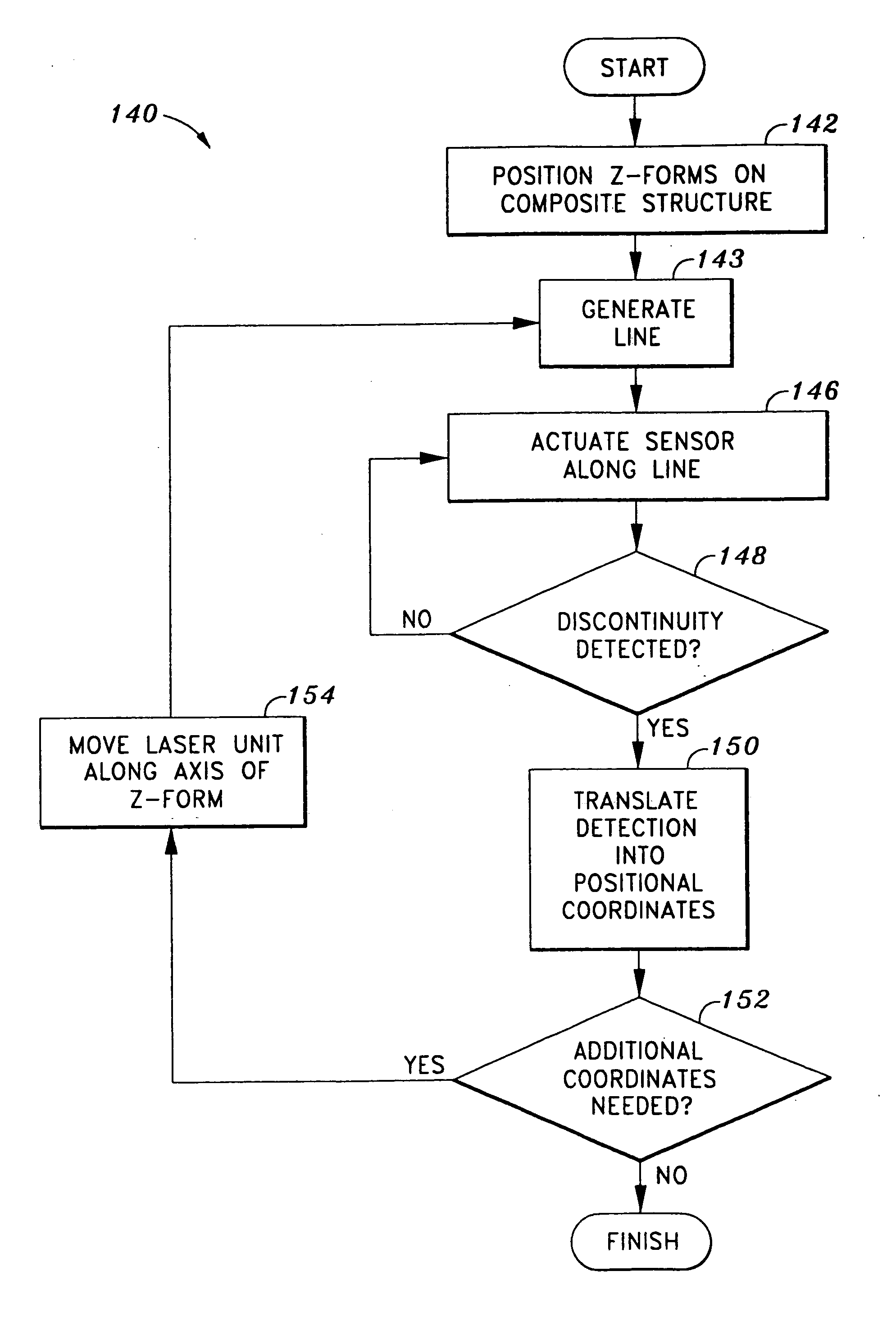
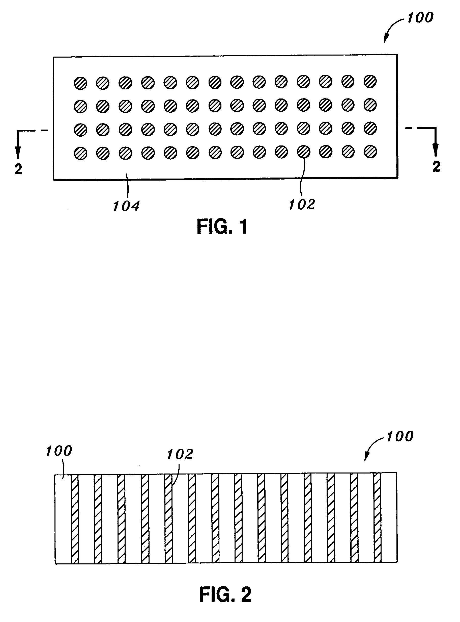
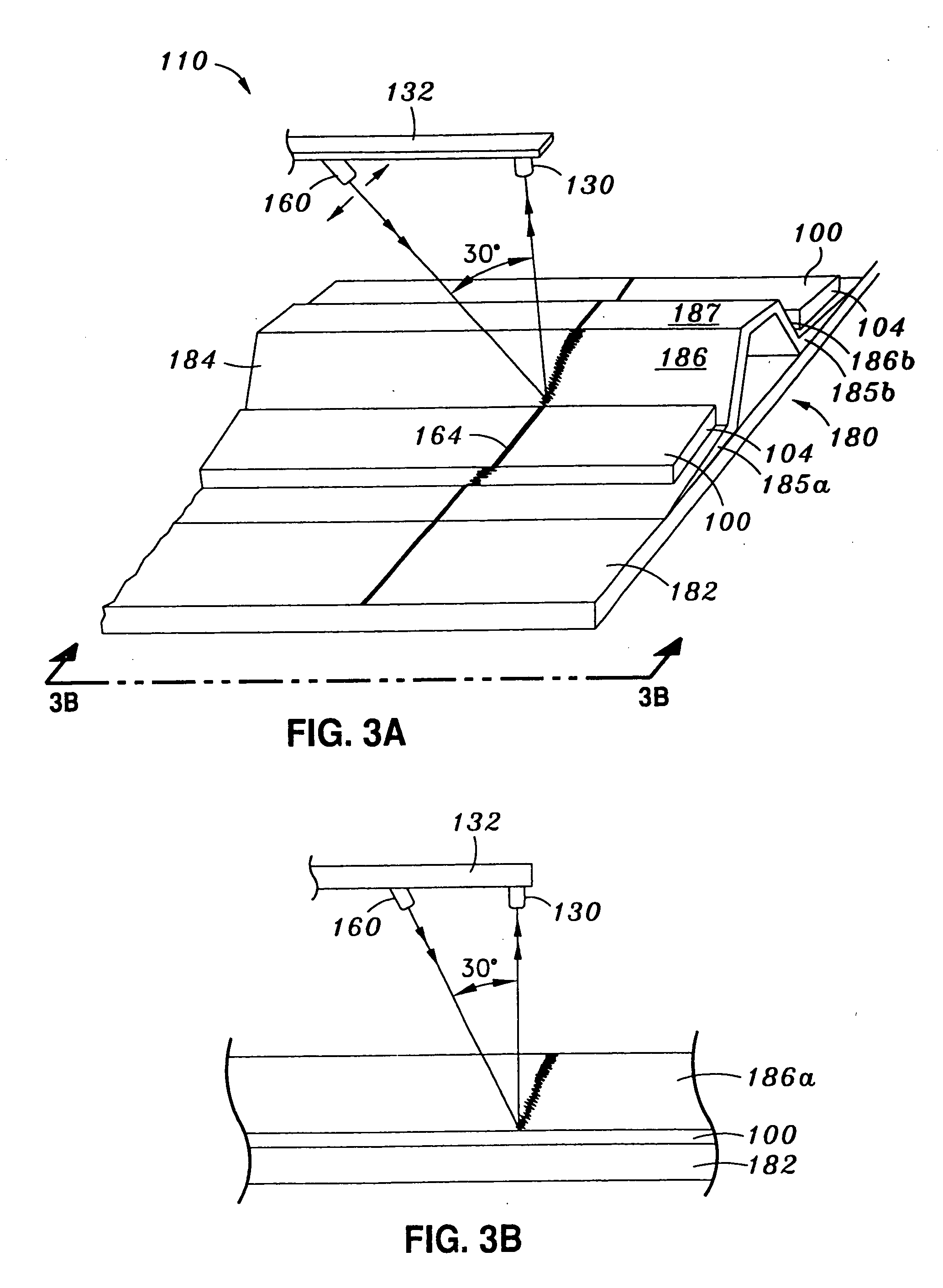
[0022] Referring now to the drawings wherein the showings are for purposes of illustrating preferred embodiments of the present invention only, and not for purposes of limiting the same, FIG. 1 and FIG. 2 illustrate one embodiment of a Z-form 100. As shown, the Z-form 100 comprises a plurality of Z-pins 102 embedded within a carrier 104. In one embodiment, the typical Z-pin 102 has a diameter of 0.011 inches and a length of 0.5 inches and is made out of a rigid material such as stainless steel, titanium, copper, graphite, epoxy, composite, glass, carbon, or the like. Typically, the manufacturer embeds an array of Z-pins 102 within the carrier 104, which is often made of a foam-like material, for shipping purposes. In one embodiment, the manufacturer embeds the Z-pins 102 at a density of 400 per square inch. As will be described in greater detail below, the Z-form 100 is positioned on an uncured composite structure, and an insertion tool moves the Z-pins 102 out of the carrier 104 an...


PUM

PropertyMeasurementUnit
angleaaaaaaaaaa
second angleaaaaaaaaaa
lengthaaaaaaaaaa

Abstract

A Z-form position detector useful for ascertaining the position of Z-forms with respect to underlying composite structure. The device comprises an oscillating laser that generates a line projected onto the Z-form and composite structure at an angle. The line appears discontinuous due to the topography of the Z-form and composite structure. For example, the line is discontinuous at the edges of the Z-form. The device further comprises a sensor sensitive to the frequency of the laser. The sensor scans along the line until a discontinuity (i.e., a break in the line) is detected. Since the discontinuity corresponds to the edge of the Z-form, detection of the discontinuity allows the device to ascertain precise coordinates of a point on the edge of the Z-form. The device thus allows Z-pins to be driven into composite structure automatically for savings on time and cost.

Description

CROSS-REFERENCE TO RELATED APPLICATIONS [0001] (Not Applicable) STATEMENT RE: FEDERALLY SPONSORED RESEARCH / DEVELOPMENT [0002] (Not Applicable) BACKGROUND OF THE INVENTION [0003] The following generally relates to positioning systems, and more specifically relates to optical systems used to automatically locate Z-forms with precision for reinforcement of composite structures. [0004] Manufacturers utilize composite materials in a wide variety of applications. The relatively high strength-to-weight ratio, stiffness-to-weight ratio, and fatigue characteristics of composites have made the material increasingly popular with aerospace, automotive, and other industries. [0005] To join individual composite parts, manufacturers often use conventional fasteners; however, the use of conventional fasteners typically requires access to both sides of the assembly, and such access can be limited. In these cases, manufacturers usually employ alternative attachment means. For example, the composite p...

Claims


Application Information

Patent Timeline
Patent Type & Authority Applications(United States)
IPC IPC(8): B29C73/10B29C73/06B29C73/24
CPCB29C73/06B29C73/10B29C73/24B29K2105/04B29L2031/3076B29L2031/608Y10S264/06
Inventor HALL, TERENCE F.W.
Owner HALL TERENCE F W
Why Eureka
Try Eureka