Screen, Fresnel lens sheet used for the same, and image display apparatus using the same

a technology of image display apparatus and lens sheet, which is applied in the direction of optics, projectors, instruments, etc., can solve the problems of reducing efficiency, increasing loss, and reducing the brightness of the upper left and right edges of the screen, and achieves the effect of reducing the size of the image display apparatus and high image quality

Inactive Publication Date: 2005-12-08
MAXELL HLDG LTD
View PDF2 Cites 4 Cited by
  • Summary
  • Abstract
  • Description
  • Claims
  • Application Information

AI Technical Summary

Benefits of technology

[0007] The thinning-down (longitudinal downsizing) of the set can be achieved by reducing the projection distance by use of a wider-angle projection-lens and further shifting the optical-axis center of the projection lens downward with respect to the center of the transmissive screen (e.g., aligning the optical-axis center of the projection lens with the central lower end of the transmissive screen).
[0011] Accordingly, for a transmissive screen responding to the thinning-down of the set, it is important to reduce the reflection loss of light on the entrance plane of the screen and to improve utilization efficiency of the light and make the image brighter (i.e., suppressing decreases in the brightness of the image). It is also important to suppress the discontinuity of the light.
[0018] According to the present invention, it becomes possible to thin down an image display apparatus while at the same time obtaining high image quality.

Problems solved by technology

Further thinning-down of the set abruptly increases the loss and the upper left and right ends of the screen decrease in brightness.
In the configuration described in Patent Document 1, however, since the configuration has refractive prisms on the light entrance surface of the Fresnel lens sheet, efficiency decreases and particularly a medium-band image (on the screen, a donut-like range) important for obtaining high image quality becomes dark.
If the discontinuity of light actually occurs, the image when viewed from the front will include discontinuous sections and image quality will deteriorate.

Method used


Image

  • Screen, Fresnel lens sheet used for the same, and image display apparatus using the same
  • Screen, Fresnel lens sheet used for the same, and image display apparatus using the same
  • Screen, Fresnel lens sheet used for the same, and image display apparatus using the same

Examples


first embodiment

(1) First Embodiment

[0030]FIG. 1 is a partially sectional, perspective view showing an example of an image display apparatus according to the present invention. An image generation source 1 includes a projection cathode-ray tube or a reflective or transmissive liquid-crystal panel, an image modulation element such as a display element having a plurality of very small mirrors, and other elements, and displays an image. Although a projection lens 2 projects the image onto a transmissive screen 3, since the projection lens is generally long in projection distance, a reflecting mirror 4 is provided halfway on an optical path thereof to reduce the depth (longitudinal dimension) of the image display apparatus. These elements are fixed to a desired position inside a frame 5.

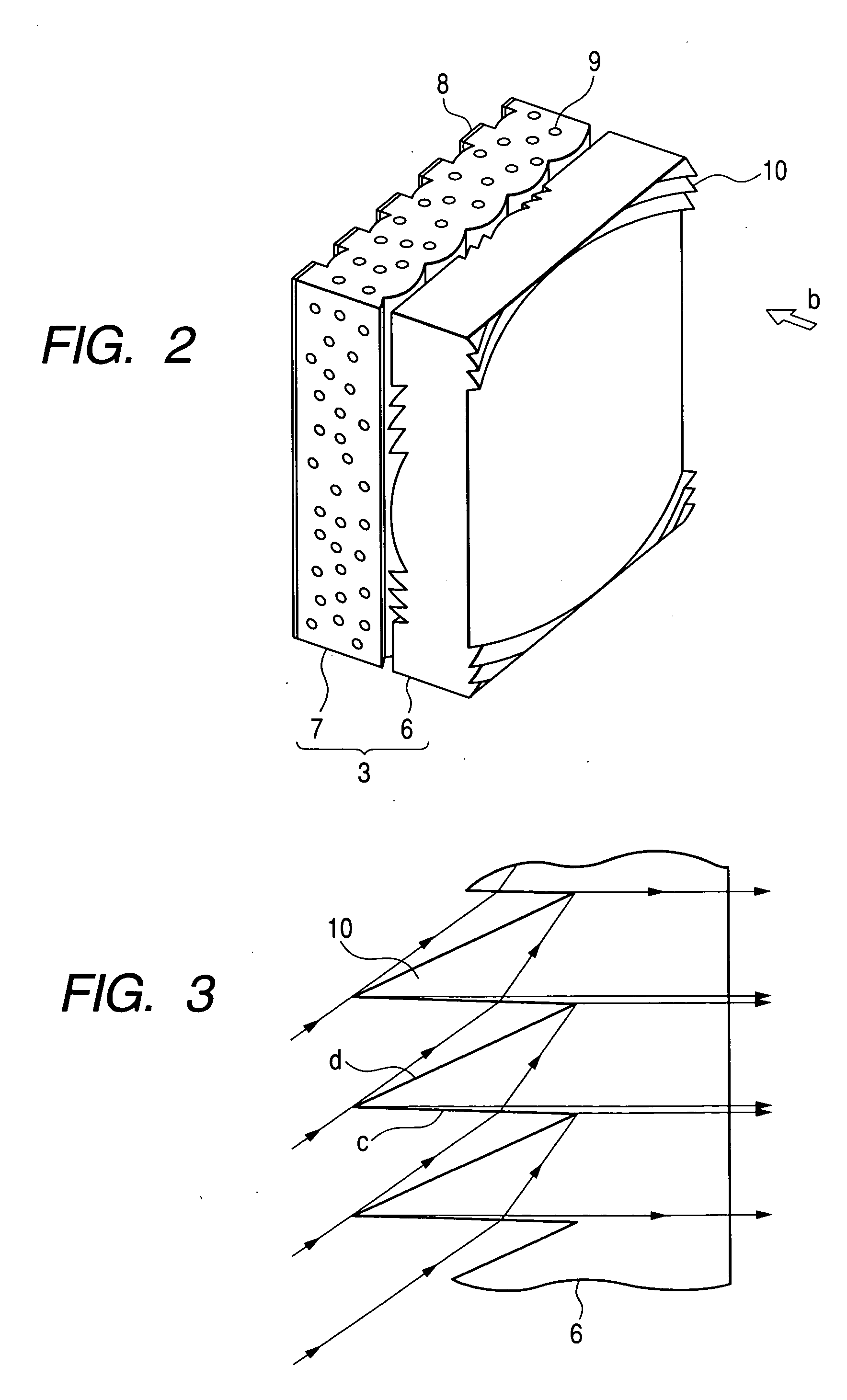
[0031]FIG. 2 is a schematic view showing a structure of a transmissive screen 3 according to the present invention. The enlarged image (not shown) projected from a direction of an arrow “b” is converted, at a Fresnel l...

second embodiment

(2) Second Embodiment

[0040]FIG. 5 is a longitudinal sectional view of a second embodiment of the Fresnel lens sheet 6 according to the present invention, and shows in enlarged form the interface between the totally reflective prisms 10 and the planar section 12. In FIG. 5, the same reference numbers as in FIG. 4 denote the same components. FIG. 5 differs from FIG. 4 in that the connection face “g” is a rough face. It has been described in the first embodiment that when exit rays from a totally reflective prism 10 enter an associated refractive prism 41, most of the light exits as image light, and part of the light returns to that refractive prism 41 to become stray light, part of which then further exits downward. The amount of downward exiting light of all exit light mentioned above is almost unnoticeably slight. On closer observation, however, one will notice the downward exiting light appear as a thin concentric white line. In the second embodiment of the present invention, even ...

third embodiment

(3) Third Embodiment

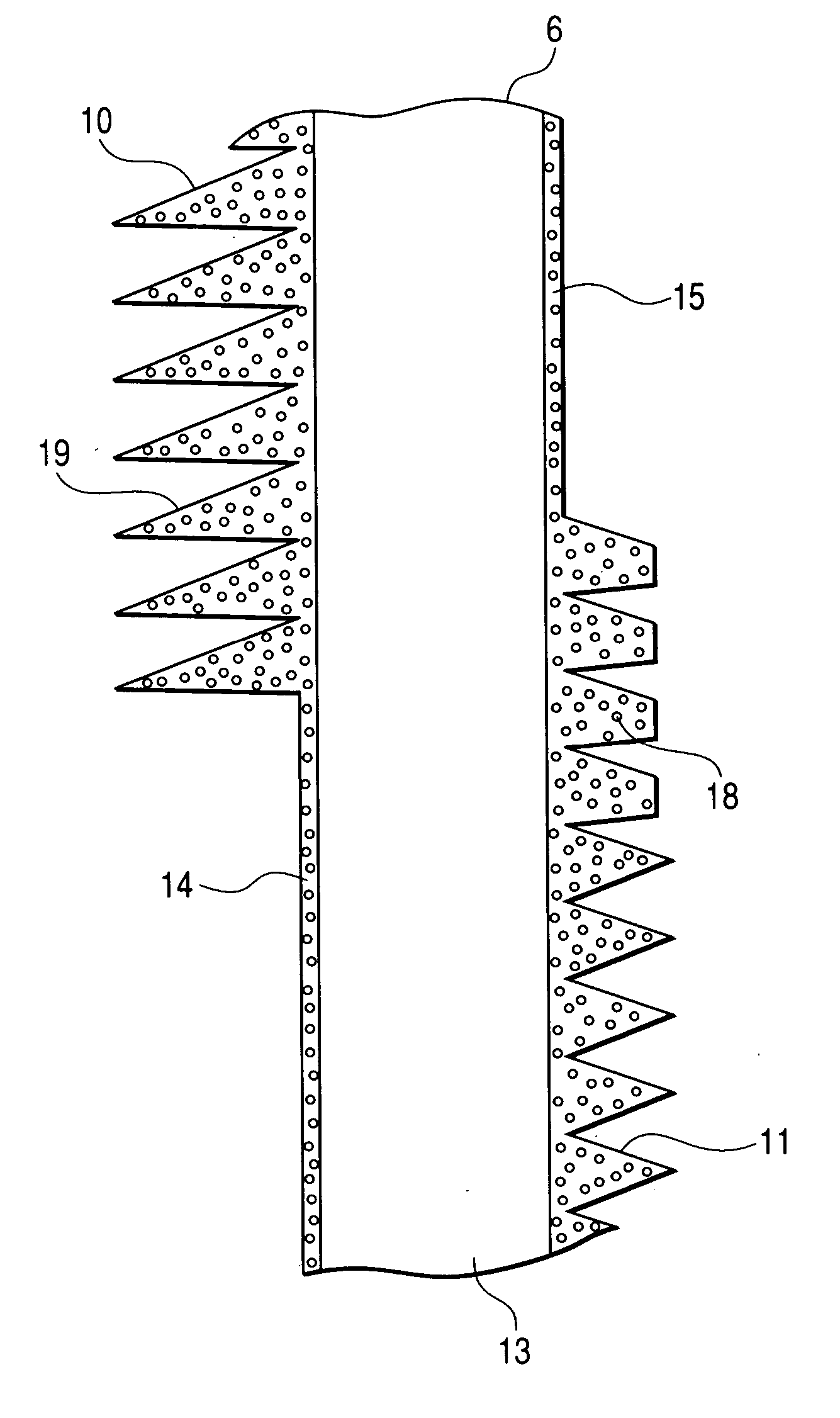
[0041] Next, a third embodiment of the present invention is described below using FIG. 7. In the present embodiment, a totally reflective prism section and a refractive prism section are molded using ultraviolet-cured-type resin. FIG. 7 is a longitudinal sectional view of a Fresnel lens sheet 6 according to the third embodiment of the present invention. On a transparent base material 13 constituting the Fresnel lens sheet 6, totally-reflective prisms 10 and refractive prisms 11 are formed using ultraviolet-cured-type resin. A thickness of an ultraviolet-cured-type resin layer on which neither the prisms 10 nor the prisms 11 are formed is approximately equal to a height of a valley of each such prism. In the present embodiment, it is possible to save the quantity of ultraviolet-cured-type resin, compared with that required when the thickness of the ultraviolet-cured-type resin layer on which neither the prisms 10 nor the prisms 11 are formed is to be made approxim...


PUM


Abstract

The present invention provides a screen suitable for reducing the longitudinal dimension of a set. The present invention includes two prism sections. One is a totally reflective prism section (10) provided at the image generation source side of a Fresnel lens sheet (6). The other is a refractive prism section (11) provided at the image-watching side of the Fresnel lens sheet. The refractive prism section (11) includes a refractive face (e) for refracting incident light and making the light exit toward the image-watching side, a plane (f) approximately parallel to the principal plane of the Fresnel lens sheet, and a connection face (g) for continuously forming the face (e) and the plane (f).

Description

CLAIM OF PRIORITY [0001] The present application claims priority from Japanese application serial no. JP2004-166549, filed on Jun. 4, 2004, the content of which is hereby incorporated by reference into this application. BACKGROUND OF THE INVENTION [0002] (1) Field of the Invention [0003] The present invention relates to an image display apparatus for enlarging the image generated by an image generation source, and displaying the image in a projection format on a transmissive screen. The invention also relates to the screen and Fresnel lens sheet used for the image display apparatus. [0004] (2) Description of the Related Art [0005] A projection type of image display apparatus (hereinafter, called the set in some cases) projects, in enlarged form onto a transmissive screen via a projection lens and / or the like, the image displayed by the projection cathode-ray tube or liquid-crystal display apparatus (or the like) that functions as a compact image generation source, and thus forms tha...

Claims


Application Information

Patent Timeline
Patent Type & Authority Applications(United States)
IPC IPC(8): G03B21/10G03B21/62
CPCG03B21/10G03B21/625
Inventor YOSHIKAWA, HIROKIOHISHI, TETSUHIRATA, KOJIIMAFUKU, DAISUKE
Owner MAXELL HLDG LTD
Why Eureka
Try Eureka