
Eureka
For R&D, Eureka makes reading and utilizing patents & technical documents easy.
Eureka AIR
Designed for self-driven R&D workflows. Generate viable solutions, solve complex R&D challenges, empower your innovation with AI.

Eureka Materials
Designed for material experts only. Revolutionize your material R&D, from search, analyze, to developing new materials.

TechResearch
Generate reliable direction feasibility study reports for your R&D in just a few steps.

TechSeek
Discover and master advanced knowledge NOW. Basics, ideas, possibilities, all at once.

TechMind
As an expert in R&D Theories, TechMind can generates customized viable solutions instantly.

TechRisk
Analyze your overall solution with one click, know your potential R&D risks in advance.

TechMonitor
Get weekly tech updates, stay abreast of the latest tech innovations and key insights.
Image forming apparatus
- Summary
- Abstract
- Description
- Claims
- Application Information
AI Technical Summary
Benefits of technology
Problems solved by technology
Method used
Image

Examples
embodiment 1
(1) An Example of an Image Forming Apparatus:
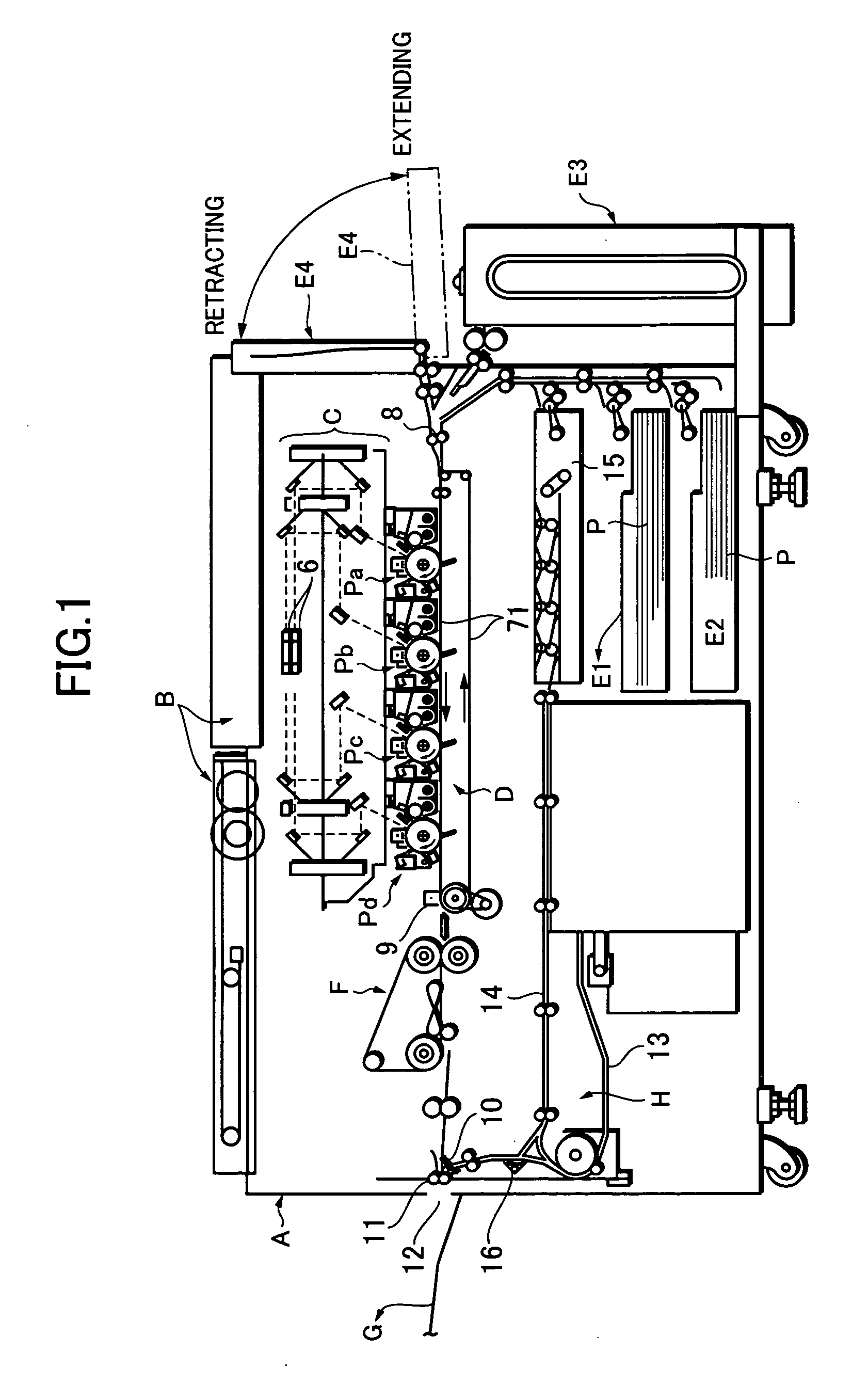
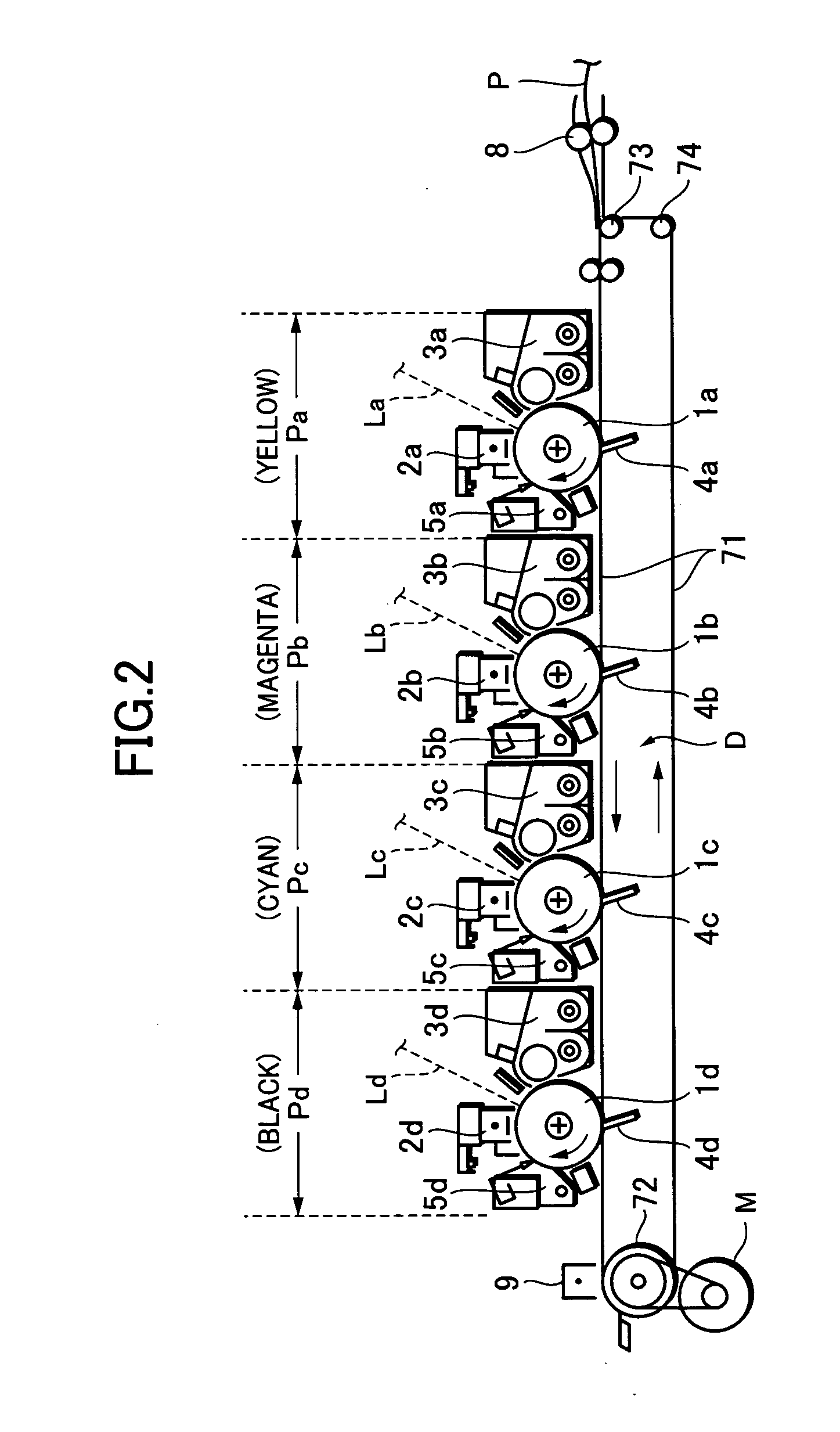
[0026]FIG. 1 is a schematic sectional view which shows a basic configuration of an example of an image forming apparatus according to the present invention, and FIG. 2 is a enlarged sectional view which shows an essential portion of the image forming apparatus shown in FIG. 1.
[0027] The image forming apparatus in this embodiment is a full color laser printer of a four-color, toner type (a four drum laser printer having a plurality of optical scanning means).
[0028] The image forming apparatus is provided therein with a transfer belt mechanism D having an endless transfer belt 71 as a recording medium carrier for carrying on its surface a recording medium P. Image forming portions Pa, Pb, Pc, Pd as four image forming means, are arranged above the transfer belt 71 in the mentioned order as viewed from the upstream side, along a belt rotating direction. The first image forming portion Pa forms an yellow toner image, the second image formi...
embodiment 2
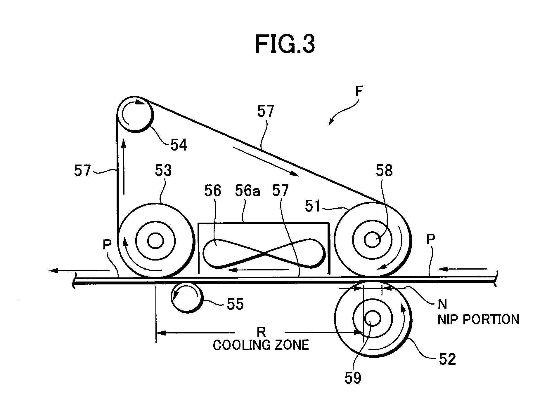
[0111] Although an explanation will be made of the image forming apparatus in the embodiment 1 in which the fixing belt 57 serving as a surface-smoothening means in the belt fixing unit F is composed of the polyimide base formed thereon with the PFA mold parting layer, in this embodiment, there is used an endless belt composed of stainless sheets (SUS) having a thickness of 100 μm, which are joined together, as the fixing belt 57. Since a metal surface of the metal belt can simply be mirror-surface polished, it can offer such a merit that a higher glossy image can be produced.
[0112] Also in this embodiment, an glossy image forming mode was carried out, similar to that in the image forming apparatus in the embodiment 1, a satisfactorily high glossy toner image could be obtained without image inferiority, such as toner height difference or blurring.
embodiment 3
[0113]FIG. 6 is a schematic sectional view illustrating a basic configuration of an image forming apparatus according to this embodiment. The configuration of this image forming apparatus in this embodiment is the same as that of the image forming apparatus in the embodiment 1 (which is shown in FIG. 1), except that a fifth paper feed portion E5 (paper feed cassette) as an exclusive paper feed portion for a recording medium P having a surface-roughened glossy layer, and a conveying path 17 exclusive for a surface-smoothening process, which introduces the recording medium P direct from the fifth paper feed portion 5E into the belt fixing unit F, bypassing the image forming portions Pa, Pb, Pc, Pd are provided. Thus, the configuration identical with that of the embodiment 1 will be omitted in order to avoid duplication of the explanation.
[0114] In this embodiment, if the glossy image forming mode is selected, the following steps are successively carried out. It is noted that a series...
PUM
 Abstract
Description
Claims
Application Information
 - R&D Engineer
- R&D Manager
- IP Professional
- Industry Leading Data Capabilities
- Powerful AI technology
- Patent DNA Extraction
Browse by: Latest US Patents, China's latest patents, Technical Efficacy Thesaurus, Application Domain, Technology Topic, Popular Technical Reports.
© 2024 PatSnap. All rights reserved.Legal|Privacy policy|Modern Slavery Act Transparency Statement|Sitemap|About US| Contact US: help@patsnap.com