
Body piercing instrument

a body piercing and instrument technology, applied in the field of ornamental piercing of body parts, can solve the problems of preventing continuous control of the exact location and timing of the ear piercing process, affecting the accuracy of the piercing process, and the drawbacks of the existing ear piercing cartridge, so as to achieve fine control and high piercing accuracy.

Active Publication Date: 2005-12-08
REIL VLADIMIR
View PDF33 Cites 18 Cited by
  • Summary
  • Abstract
  • Description
  • Claims
  • Application Information

AI Technical Summary

Benefits of technology

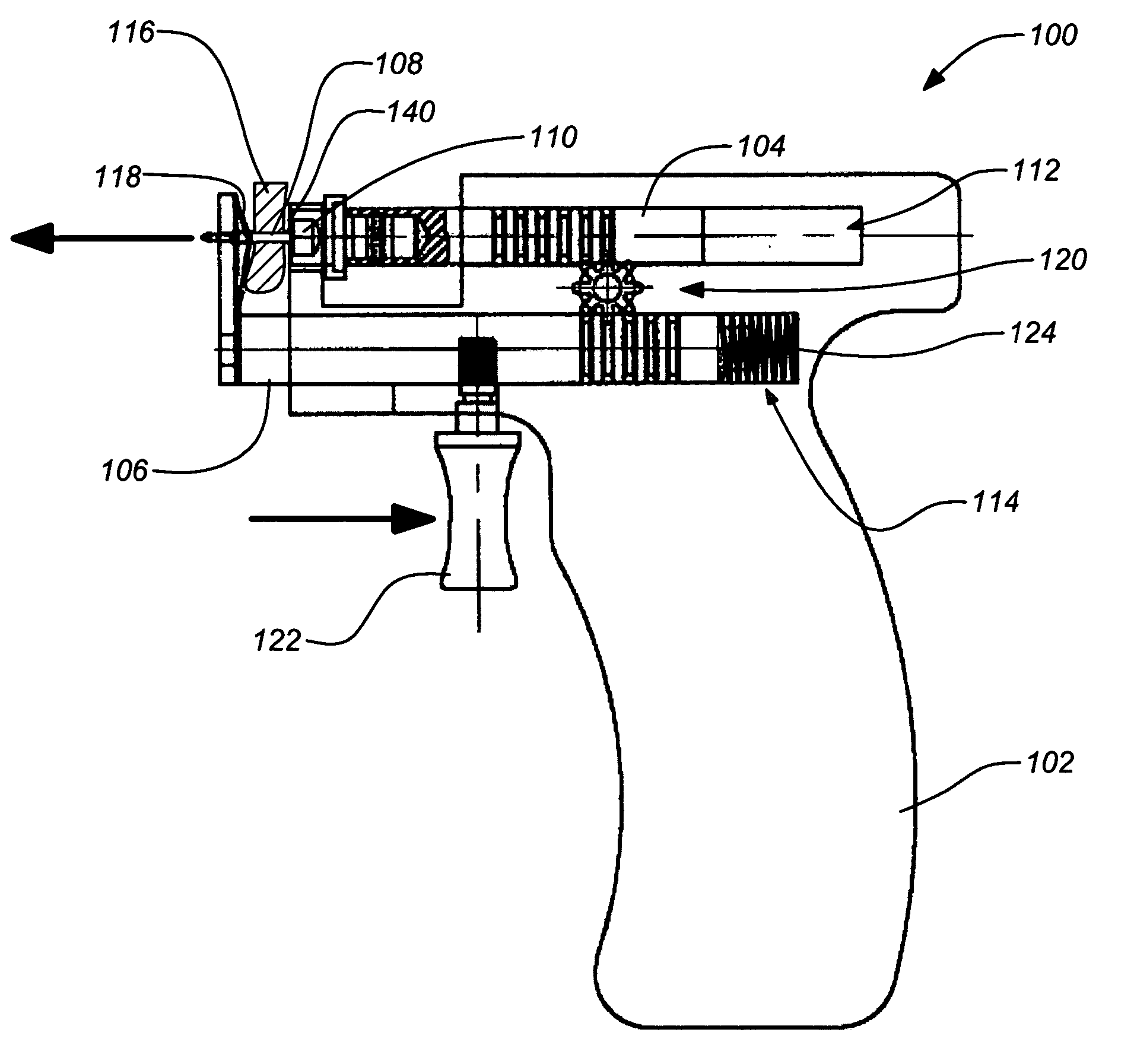
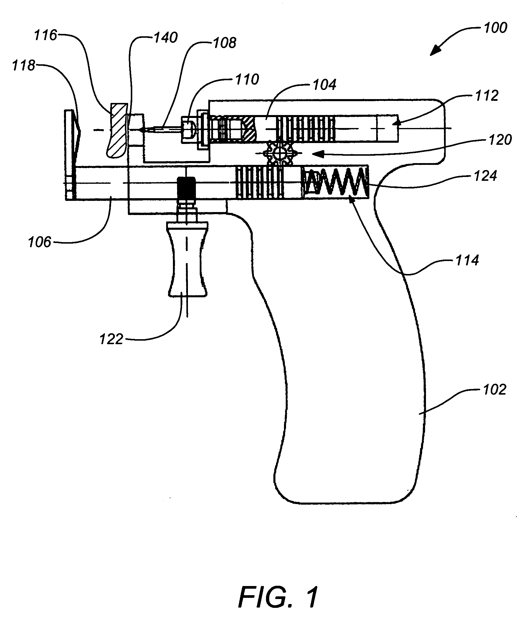
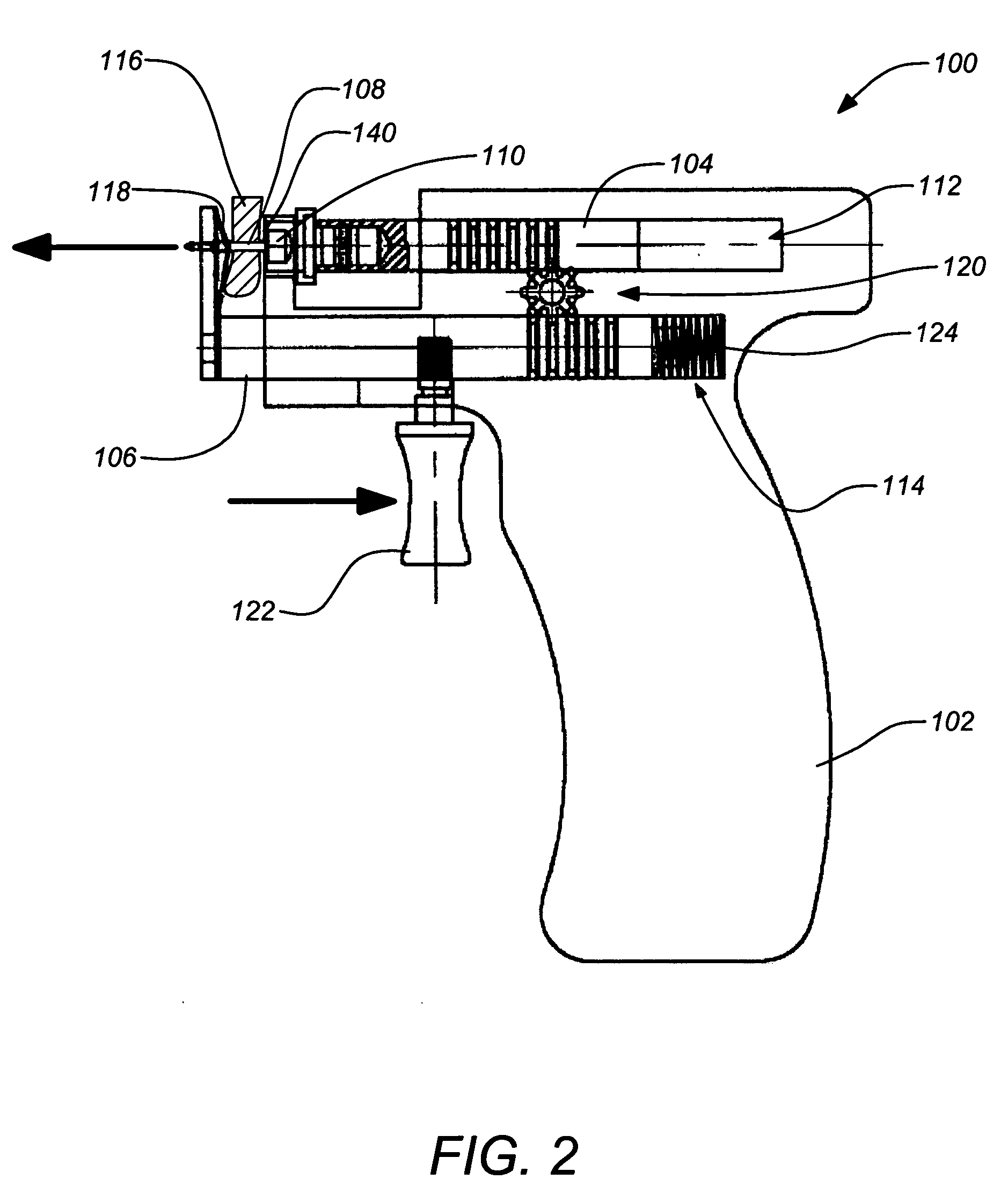
[0009] Apparatuses and methods for a ornamental piercing of body parts are disclosed. Embodiments of the present invention provide a higher level of accuracy for piercing even when handled by persons without a high degree of training or skill. In particular, the present invention seeks to provide an piercing instrument that can be finely controlled throughout the procedure by the operator. The operator need not commit to piercing until certain of piercing the precise desired location.
[0011] The body piercing instrument can be hand-operated and functions to provide a very controlled piercing operation, avoiding the snap action which can result in errors in the operation of many conventional piercing instruments. Furthermore, embodiments of the invention may also include a stabilizing surface to support the body part to be pierced during operation. The piercing instrument is placed in stable contact with the body part to be pierced before operation of the instrument. The precise location of the intended piercing can be shown with an indicator on the stabilizing surface (e.g. a passage for the post to pass through). This further enhances to the precision and control of the operation of the instrument.

Problems solved by technology

Some existing ear-piercing cartridges suffer from a number of drawbacks.
However, many piercing instruments can be erratic, particularly when the technician is unskilled.
Thus, it prevents continuous control of the exact location and timing of the ear-piercing process.
Because of the lack of continuous control over the location and timing of the ear-piercing process, the technician who is piercing the ear must use some guesswork to line the stud post with the desired piercing area.
Occasionally, this causes the technician to miss the exact location for the piercing.

Method used


Image

  • Body piercing instrument
  • Body piercing instrument
  • Body piercing instrument

Examples


Embodiment Construction

[0030] In the following description of the preferred embodiment, reference is made to the accompanying drawings which form a part hereof, and in which is shown by way of illustration specific embodiments in which the invention may be practiced. It is to be understood that other embodiments may be utilized and structural changes may be made without departing from the scope of the present invention. For example, it should be noted that although embodiments of the piercing instrument are described hereafter in the context of ear piercing, the invention is not limited to ear piercing; the piercing instrument may also be employed in piercing many other body parts as is known in the art.

[0031] 1.0 Overview

[0032] As discussed above, embodiments of the present invention comprise a body piercing instrument that provides for stable and precise operation. The invention provides synchronized motion of both the post and nut in the piercing process. In addition, a stabilizing surface can be pro...


PUM


Abstract

Apparatuses and methods for a ornamental piercing of body parts are disclosed. An exemplary a piercing instrument includes a post carrier disposed to translate in a first channel within the body piercing instrument, a nut carrier disposed to translate in second channel within the body piercing instrument in opposition to translation of the post carrier and a synchronizing mechanism between the post carrier and the nut carrier to coordinate opposing motion relative to the body piercing instrument of both the post carrier and the nut carrier simultaneously. The synchronizing mechanism can be a gear, where the post and nut carriers include racks that engage the gear. The body piercing instrument can be hand-operated and also include a stabilizing surface to support the body part to be pierced during operation.

Description

BACKGROUND OF THE INVENTION [0001] 1. Field of the Invention [0002] The present invention relates to apparatuses and methods for ornamental piercing of body parts. Particularly, the present invention relates to apparatuses and methods for a hand-operated body piercing instrument. [0003] 2. Description of the Related Art [0004] In recent years, body piercing has become an increasingly common practice in the U.S. and throughout the world. The practice is rapidly becoming a routine procedure, often performed by laypersons without medical experience or training. Presently, a number of manually operated devices are available that allow for the safe, hygienic, user-friendly piercing of body parts. Examples of such systems are disclosed in U.S. Pat. No. 5,496,343 issued to Reil on Mar. 5, 1996, U.S. Pat. No. 5,792,170 issued to Reil on Aug. 11, 1998, U.S. Pat. No. 5,868,774 issued to Reil on Feb. 9, 1999, U.S. Pat. No. 6,599,306 issued to Reil on Jul. 29, 2003 and U.S. patent application S...

Claims


Application Information

Patent Timeline
IPC IPC(8): A61B17/34A44C7/00
CPCA44C7/001A44C7/00
Inventor REIL, VLADIMIR
Owner REIL VLADIMIR
Learn More