Sub-ambient refrigerating cycle

a sub-ambient and refrigerating cycle technology, applied in the field of cooling techniques, can solve the problems of large heat generation, large consumption of power, large size of suitable refrigeration units, etc., and achieve the effects of less power, large cooling capacity, and high degree of heat transfer

Inactive Publication Date: 2005-12-15
RAYTHEON CO
View PDF99 Cites 20 Cited by
  • Summary
  • Abstract
  • Description
  • Claims
  • Application Information

AI Technical Summary

Benefits of technology

[0006] Embodiments of the invention may provide numerous technical advantages. Some embodiments may benefit from some, none, or all of the following advantages. According to one embodiment, an efficient, lightweight refrigeration system is provided that has a large cooling capacity, but requires less power than conventional refrigeration systems. In particular, cooling may occur in an ambient environment having a temperature greater than the heat-generating structure that is being cooled. In some embodiments water is used as a refrigerant and provides a high degree of heat transfer, enabling an efficient heat transfer system. In addition, water does not result in harmful effects to the environment associated with many common refrigerants. Such a system may also allow for the use of a smaller heat exchanger than would otherwise be required.

Problems solved by technology

In contrast, there are other circuits that consume large amounts of power, and produce large amounts of heat.
However, suitable refrigeration units are large, hefty and consume many kilowatts of power in order to provide adequate cooling.
The combination of high flow rates and high pressure causes high compressor work.
Thus, although refrigeration units of the above type have been generally adequate for their intended purposes, they have not been satisfactory in all respects.
Given that there is an industry trend towards even greater power consumption in heat dissipation in certain types of electronics, such as phased array antenna systems, continued use of conventional refrigeration-based cooling systems would continue to result in even greater size, weight and power consumption, which is undesirable.

Method used


Image

  • Sub-ambient refrigerating cycle
  • Sub-ambient refrigerating cycle
  • Sub-ambient refrigerating cycle

Examples


Embodiment Construction

[0011] Example embodiments of the present invention and its advantages are best understood by referring to FIGS. 1 and 2 of the drawings, like numerals being used for like and corresponding parts of the various drawings.

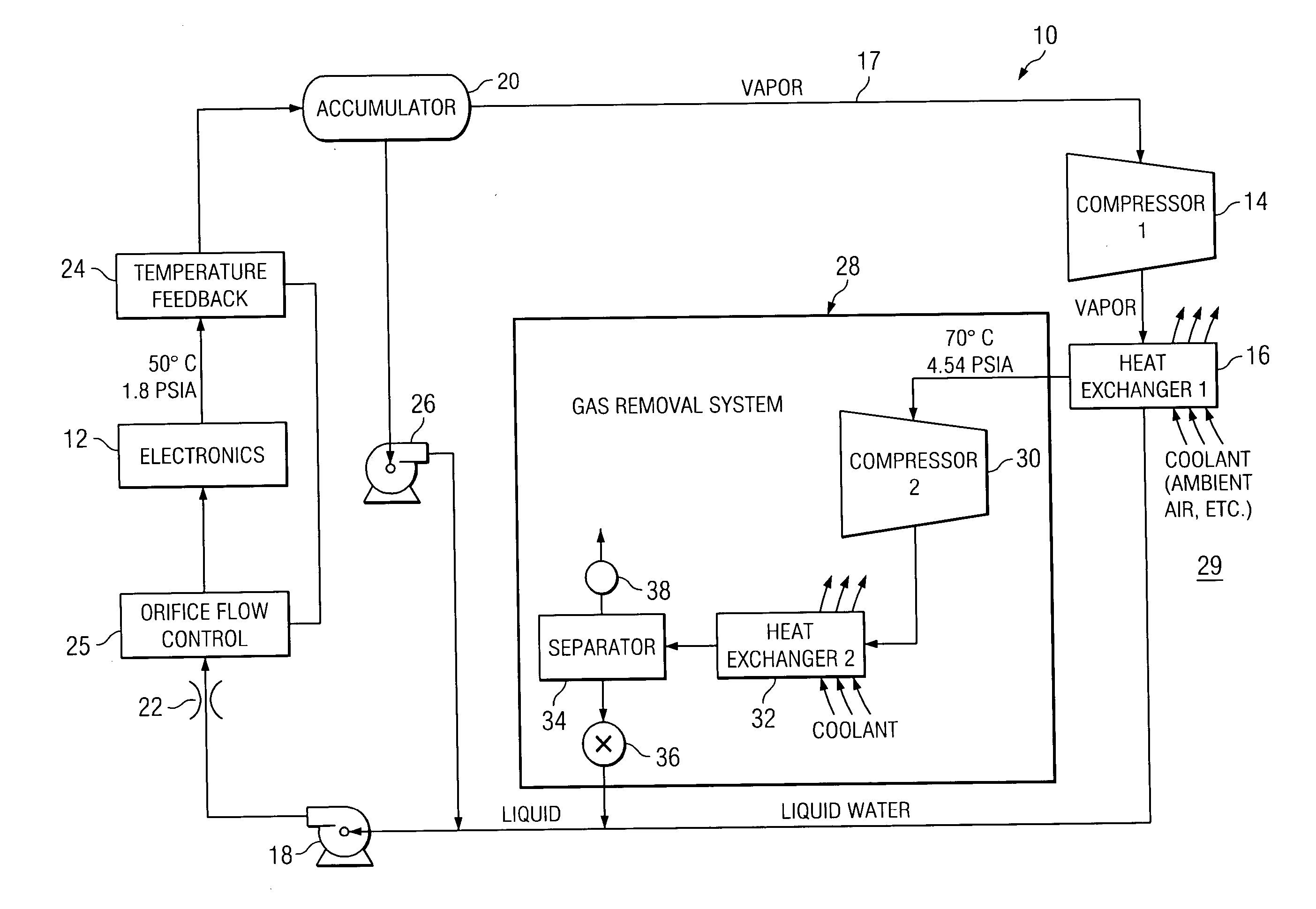
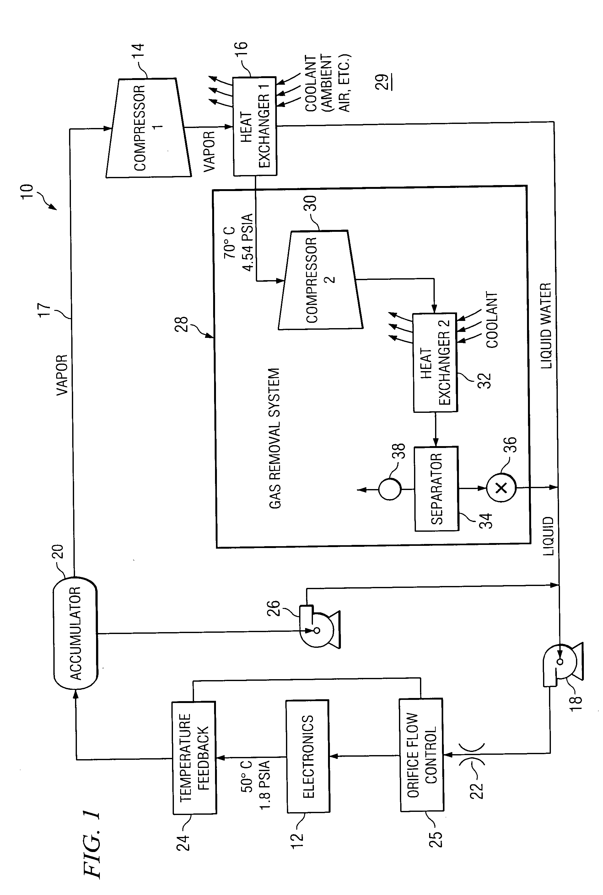
[0012]FIG. 1 is a block diagram of a system 10 for cooling according to the teachings of the invention. As illustrated, system 10 includes heat-generating structure 12, which in this example is electronic circuitry and, in particular, is a phased array antenna. Although electronic circuitry is used as an example for heat-generating structure 12, system 10 may be used to cool any suitable heat-generating structure, including use as a home cooling system. In that example, an electronic cold plate may be in thermal communication with both the phased array antenna and refrigerant within a refrigeration loop 17, as described below. System 10 also has a compressor 14 and a heat exchanger 16 included within the refrigeration loop 17.

[0013] A refrigerant within cooling loo...


PUM


Abstract

According to one embodiment of the invention, a method for cooling heat-generating structure disposed in an environment having an ambient pressure includes providing a fluid refrigerant and reducing a pressure of the refrigerant to a first sub-ambient pressure at which the refrigerant has a boiling temperature less than a temperature of the heat-generating structure. The method also includes bringing the refrigerant at the first sub-ambient pressure into thermal communication with the heat-generating structure, so that the refrigerant boils and vaporizes to thereby absorb heat from the heat-generating structure. The method further includes increasing a pressure of the vaporized refrigerant above the first sub-ambient pressure to a second sub-ambient pressure.

Description

TECHNICAL FIELD OF THE INVENTION [0001] This invention relates in general to cooling techniques and, more particularly to a method and apparatus for cooling a system that generates a substantial amount of heat. BACKGROUND OF THE INVENTION [0002] Some types of electronic circuits use relatively little power, and produce little heat. Circuits of this type can usually be cooled satisfactorily through a passive approach, such as convection cooling. In contrast, there are other circuits that consume large amounts of power, and produce large amounts of heat. One example is the circuitry used in a phased array antenna system. [0003] Electronic circuits and other structures that generate relatively large amounts of heat may be cooled through well know refrigeration systems. However, suitable refrigeration units are large, hefty and consume many kilowatts of power in order to provide adequate cooling. One reason for this is that typical refrigerants in these types of systems tend to have a l...

Claims


Application Information

Patent Timeline
Patent Type & Authority Applications(United States)
IPC IPC(8): F25B43/04F25B1/00
CPCF25B1/00F25B43/043
Inventor WYATT, WILLIAM GERALD
Owner RAYTHEON CO
Why Eureka
Try Eureka