
Apparatus and method for mr examination, and temperature control system and method

Inactive Publication Date: 2014-09-04
KONINKLIJKE PHILIPS ELECTRONICS NV
View PDF0 Cites 8 Cited by
  • Summary
  • Abstract
  • Description
  • Claims
  • Application Information

AI Technical Summary

Benefits of technology

The present invention provides an improved temperature control system for MR examinations that prevents the individual from feeling cold or sweating during the examination. The system uses a cooling device that adjusts its operation based on the individual's heating experience during the examination. This allows the individual to feel comfortable at the start of the examination and prevents them from feeling too warm or sweating during the examination. The cooling device can be applied to different body regions and can be integrated into the examination table or the coil array. The system also allows for automatic adjustment of the cooling device based on the detected temperature of the individual, which increases the efficiency and accuracy of the temperature control. Overall, the invention improves the comfort of the individual and enhances the quality of the MR images.

Problems solved by technology

One consequence of using MR apparatus, however, is that the subject is typically exposed to significant amounts of radio-frequency (RF) energy during an examination.
Nevertheless, some MRI scan protocols still impart substantial amounts of RF energy to the body of the individual examined.
Because the individual is often surrounded or enclosed by coil arrays on a bed or table during the MR examination, these can act as thermal insulators and impair the dissipation of any heat generated.
As an example, while the metabolic heat generation of a person is typically about 100 W, the RF energy imparted to an individual during examination with a conventional MRI apparatus can easily be in the range of 200 to 300 W. As such, this RF energy creates an additional heat load for the individual and can lead to sweating, discomfort, an increase in body core temperature, and may also impose restrictions on the MRI scan protocols to be applied.
That system does not, however, address the more general issue of sweating and discomfort in the absence of an implant.
While the provision of an air-conditioned clinical treatment room for conducting an MR examination is known, this in itself does not address the issue of localized heating and discomfort of the individual during an MR examination.

Method used


Image

  • Apparatus and method for mr examination, and temperature control system and method
  • Apparatus and method for mr examination, and temperature control system and method

Examples


Embodiment Construction

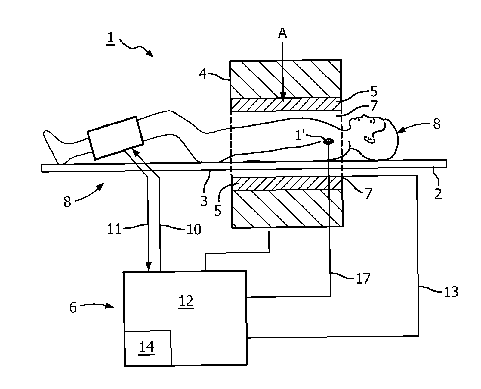
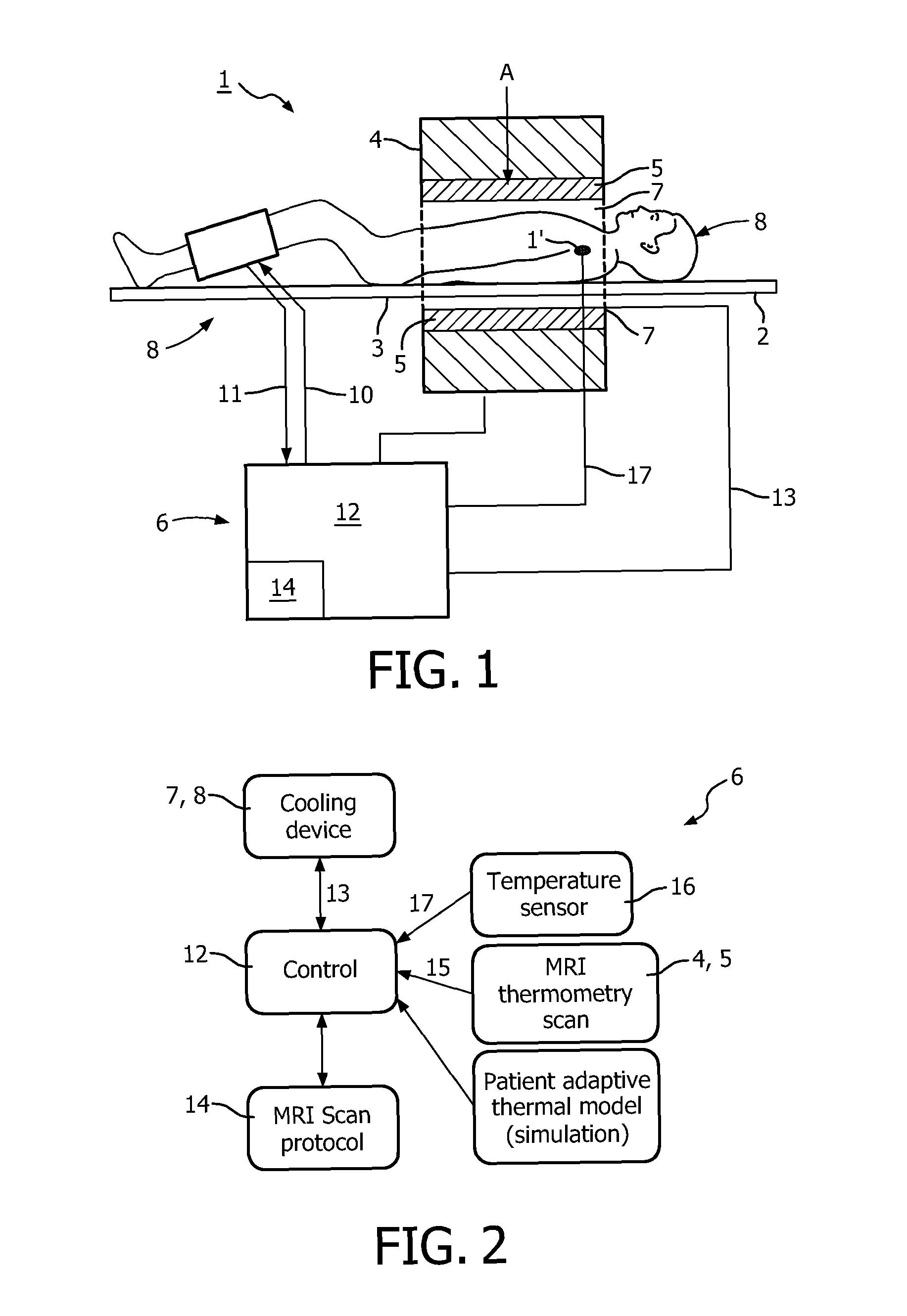
[0034]With reference firstly to FIG. 1 of the drawings, an ultra high field magnetic resonance imaging (MRI) apparatus 1 for magnetic resonance (MR) examination of subject S (in this case, a human subject or individual) according to a preferred embodiment is shown. The individual S is resting in a horizontal posture on a table 2 of the apparatus 1 with that part of the individual's body (i.e. torso) to be examined or imaged being accommodated in an examination region or space 3 formed by a cylindrical cavity formed in a housing 4 of the apparatus 1. As is known in the art, the MRI apparatus 1 includes one or more powerful magnet, gradient coils and a radio-frequency (RF) system 5 having an RF coil for transmission of a RF signal or field into the cylindrical examination region 3 in the direction of arrow A during the MR examination, all of these components forming a MR generation unit and being conveniently housed within the housing 4. The cylindrical cavity in the housing 4 which f...


PUM


Abstract

The invention provides an apparatus (1) for magnetic resonance (MR) examination of a subject (S), comprising: an examination region (3) for accommodating the subject (S) during the MR examination; a radio-frequency system (5) for transmission of a radio-frequency (RF) signal or field into the examination region (3) during the MR examination; and a temperature control system (6) for controlling the temperature of the subject (S) in the examination region (3) during the examination. The temperature control system (6) is configured to actively control or regulate an environment of the subject (S), and thereby the temperature or thermal comformt of the subject (S) based upon a detected and / or an expected temperature of the subject (S) during the MR examination. The invention also provides a method of controlling thermal comfort of the subject (S) during an examination of the subject (S) in a MR apparatus (1), comprising the steps of: estimating and / or detecting a temperature of the subject (S) during the MR examination, and actively controlling or regulating the environment of the subject (S) based upon the estimated and / or detected temperature of the subject (S) during the MR examination.

Description

FIELD OF THE INVENTION[0001]The present invention relates to the field of magnetic resonance (MR), and more particularly to an apparatus and method for magnetic resonance (MR) examination of a subject, especially a human, as well as to a temperature control system and method for a MR apparatus and to a computer program product for implementing the method of the invention.BACKGROUND OF THE INVENTION[0002]Magnetic resonance (MR) apparatus, and particularly magnetic resonance imaging (MRI) apparatus, have become important tools in the examination of individuals for the analysis and assessment of a whole range of different conditions. One consequence of using MR apparatus, however, is that the subject is typically exposed to significant amounts of radio-frequency (RF) energy during an examination. The specific absorption rate (SAR) of RF energy by individuals who undergo examination with a MR apparatus is therefore the subject of strict regulation in various countries.[0003]Nevertheless...

Claims


Application Information

Patent Timeline
IPC IPC(8): G01R33/31G01R33/44A61B5/055
CPCG01R33/31G01R33/44A61B5/055G01R33/28G01R33/288G01R33/4804A61F7/10A61F2007/0056A61F2007/0086A61B2090/3954
Inventor VAN DEN BRINK, JOHAN SAMUELHARVEY, PAUL ROYSTONFORTHMANN, PETERLEUSSLER, CHRISTOPHVERNICKEL, PETERWULBERN, JAN HENDRIKGRAESSLIN, INGMAR
Owner KONINKLIJKE PHILIPS ELECTRONICS NV
Learn More