Thermopile and automobile exhaust waste heat generation and refrigeration device employing same

A technology of thermoelectric power generation and thermopile, which is applied in the field of refrigeration technology and automobile exhaust waste heat power generation, and can solve the conversion efficiency of thermoelectric power generation devices, the space occupied by manufacturing costs, the wide application of thermoelectric thermoelectric power generation and refrigeration technology, and the integration of thermopile thermoelectric modules Low temperature, low thermocouple electromotive force, etc., to eliminate adverse effects, save welding process, and improve thermoelectric conversion rate

Inactive Publication Date: 2015-04-29
张红碧 +1
View PDF9 Cites 9 Cited by
  • Summary
  • Abstract
  • Description
  • Claims
  • Application Information

AI Technical Summary

Problems solved by technology

Although semiconductor thermoelectric power generation has been used in many applications, the integration of thermopile (or thermoelectric module), which has played a key role for a long time, is not high, resulting in the conversion efficiency, space occupied and manufacturing cost of thermoelectric power generation devices limiting thermoelectric thermoelectric power generation and refrigeration. Wide application of technology in automobiles
In the current thermopile, there are enough r...

Method used


Image

  • Thermopile and automobile exhaust waste heat generation and refrigeration device employing same
  • Thermopile and automobile exhaust waste heat generation and refrigeration device employing same
  • Thermopile and automobile exhaust waste heat generation and refrigeration device employing same

Examples


Embodiment Construction

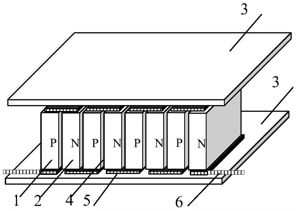
[0020] The present invention will be further described below in conjunction with the accompanying drawings and specific embodiments. Such as figure 1 As shown, the interior of the thermopile of the present invention includes a plurality of thermocouples connected in series. Each thermocouple is composed of a P-type thermocouple arm 1 and an N-type thermocouple arm 2, and is packaged in a housing. Type thermocouple arms 1 and N type thermocouple arms 2 are arranged in a staggered order, and are connected by inserting heat-insulating insulating film material 4 between adjacent sides. Each pair of adjacent P-type thermocouple arms 1 and N-type thermocouple arms The upper bottom surface of 2 is connected to form a thermocouple through the thermally conductive electrode material 5, and each thermocouple is sequentially connected to the thermally conductive electrode material 5 through the lower bottom surface of its thermocouple arm to form a series circuit, and the lower bottom su...


PUM


Abstract

Various types of automobile exhaust waste heat generation devices at present are complex in process, high in cost, low in integration level, large in size and low in heat-electricity conversion efficiency. The invention discloses a thermopile which is high in integration level, simple in structure, low in cost and high in reliability; the invention also discloses an automobile exhaust waste heat generation and refrigeration device employing the thermopile as a core part for generation and refrigeration. P-type thermocouple arms formed in the shape of a rectangular cylinder and N-type thermocouple arms are arranged in a staggered manner. A heat-insulation and insulting film material is arranged between the adjacent thermocouple arms in an attaching manner for isolation, so that the convection of air is eliminated, the defect of the reduction of the temperature difference between cold and hot surfaces caused by radiation is overcome, and the heat-electricity conversion efficiency is improved. The electric connection between the thermocouple arms is achieved through flexible heat-conduction and electric-conduction materials, so that a thermal stress is alleviated, the adverse effect of the thermal stress on a product is eliminated, and the problem that the reliability and the service life of the product are affected seriously, caused by the deformation and cracking of the thermopile and falling of welding spots between the thermocouple arms which are caused by the thermal stress, is solved.

Description

technical field [0001] The invention is related to temperature difference thermoelectric power generation and thermoelectric refrigeration technology, especially related to automobile tail gas waste heat power generation and refrigeration technology. Background technique [0002] Semiconductor thermoelectric power generation technology uses the Seebeck effect to directly convert thermal energy from temperature difference into electrical energy. It has the advantages of small size, light weight, no vibration, no noise, and long life. It has broad prospects for industrial waste heat or waste heat utilization. Although semiconductor thermoelectric power generation has been used in many applications, the integration of thermopile (or thermoelectric module), which has played a key role for a long time, is not high. As a result, the conversion efficiency, space occupied and manufacturing cost of thermoelectric power generation devices limit thermoelectric thermoelectric power gener...

Claims


Application Information

Patent Timeline
IPC IPC(8): H01L35/32F25B21/04B60H1/32
Inventor 张红碧许小燕曾东建
Owner 张红碧
Why Eureka
Try Eureka