Vacuum system communication

a vacuum system and communication technology, applied in the field of vacuum system communication, can solve the problems of small vacuum pump capacity, increased airflow in the system, etc., and achieve the effects of improving surveillance, saving energy, and even vacuum level

Inactive Publication Date: 2005-12-15
DELAVAL HLDG AB
View PDF8 Cites 8 Cited by
  • Summary
  • Abstract
  • Description
  • Claims
  • Application Information

AI Technical Summary

Benefits of technology

[0020] An advantage of the present invention is that energy savings is obtained in an automatic milking system.
[0021] A further advantage is that better surveillance is obtained over the function of the vacuum pump system.
[0022] Yet a further advantage is that control is achieved over the vacuum pump system by the automatic milking system.
[0023] A further advantage of the present invention is that an even vacuum level with few fluctuations can be achieved in the milking system when the vacuum system controller is instructed to raise the vacuum before the need for higher vacuum levels arise.

Problems solved by technology

This is difficult to achieve, because such incidents can cause airflow in the system to increase over what is needed when the system is operating properly.
The problem with this arrangement is that only a small portion of the vacuum pump capacity is actually needed for milking, with majority of the airflow passing through the regulator.
A further problem is how to achieve better surveillance and monitoring of the workings of the vacuum pump system.

Method used


Image

  • Vacuum system communication
  • Vacuum system communication
  • Vacuum system communication

Examples


Embodiment Construction

[0031] In the following description, for purposes of explanation and not limitation, specific details are set forth, such as particular techniques and applications in order to provide a thorough understanding of the present invention. However, it will be apparent to one skilled in the art that the present invention may be practiced in other embodiments, which depart from these specific details. In other instances, detailed descriptions of well-known methods and apparatuses are omitted so as not to obscure the description of the present invention with unnecessary details.

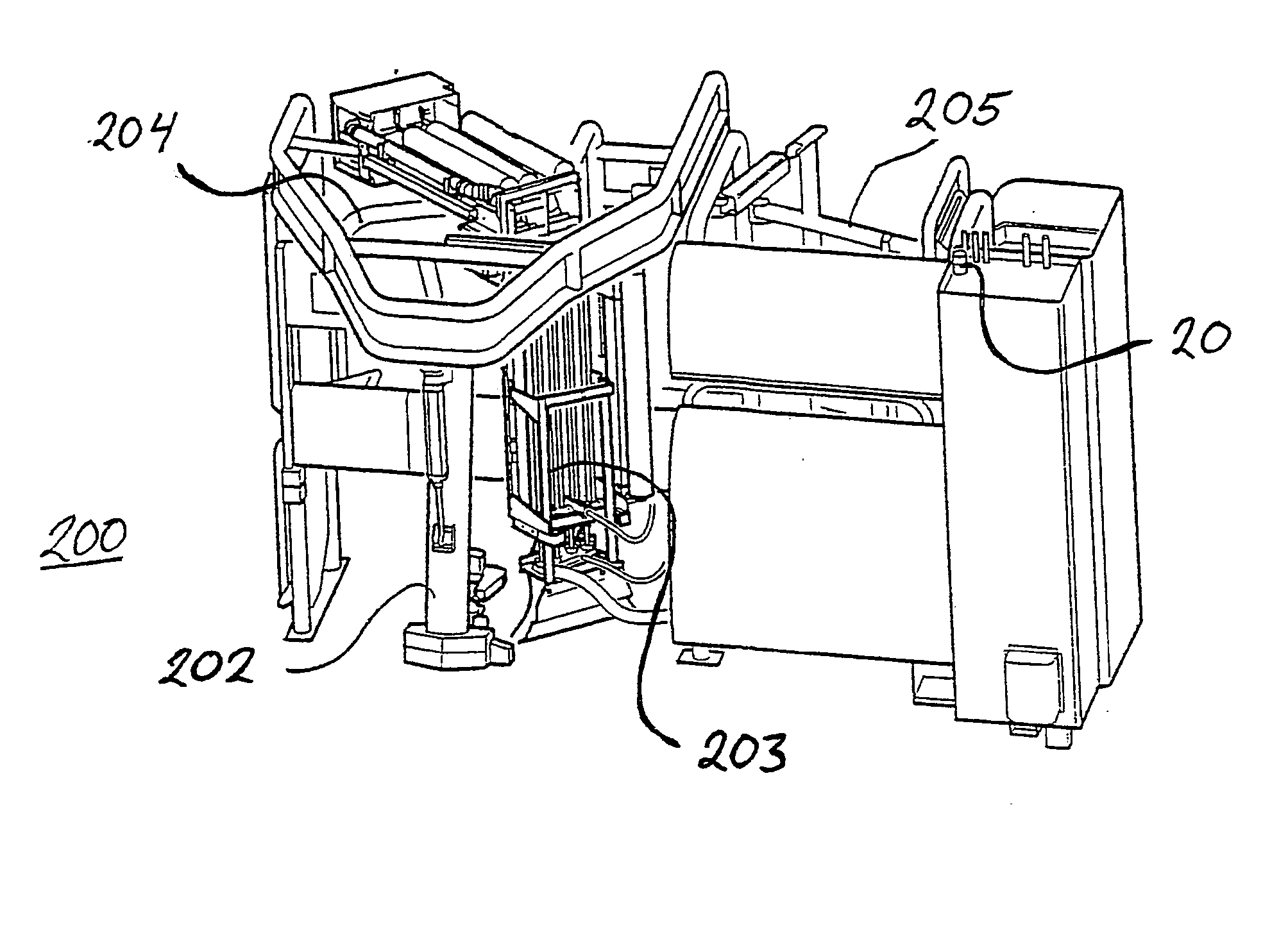
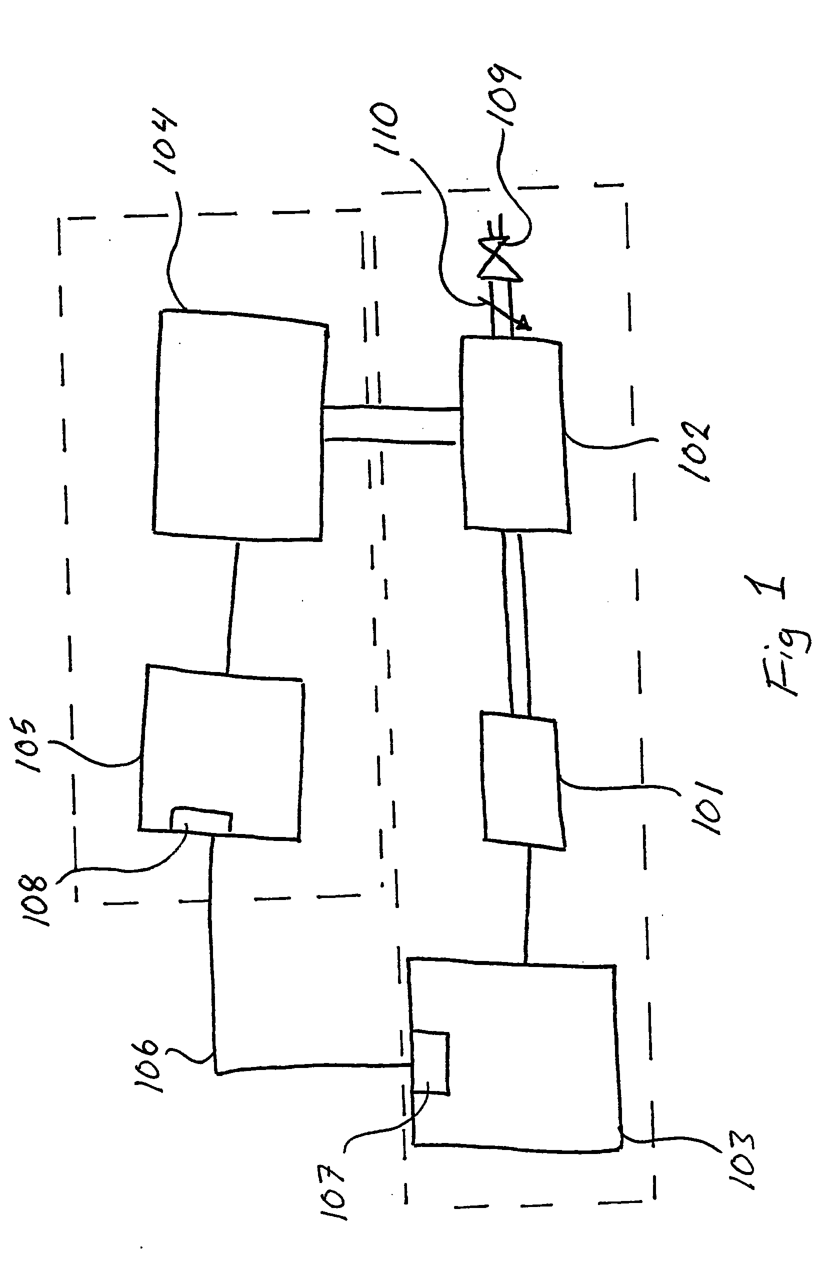
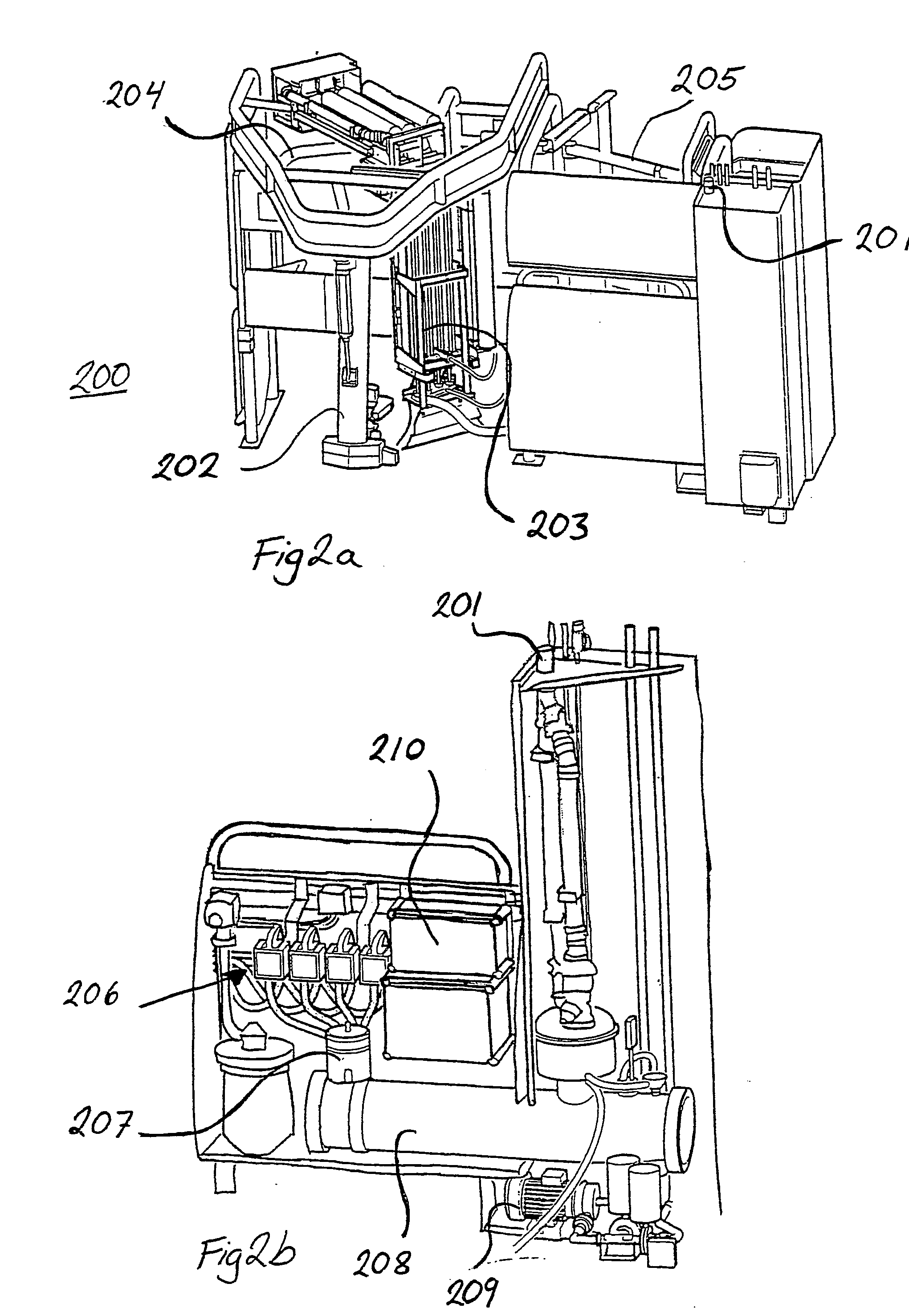
[0032]FIG. 1 shows a schematic diagram of a device according to the present invention. A vacuum pump arrangement 101 is connected to a vacuum ballast or distribution tank 102. A vacuum system controller 103 controls the vacuum pump arrangement 101 including a VSD (Variable Speed Drive) (not shown) controlling a motor (not shown). The ballast tank 102 is in turn connected to an automatic milking system 104, having a ...


PUM


Abstract

The present invention relates to controlling vacuum parameters relating to a vacuum pump arrangement in a automatic milking system, said automatic milking system comprising a vacuum pump arrangement (101), said automatic milking system comprises a milking system controller (105) arranged to control milking system parameters and said vacuum pump arrangement comprises a vacuum system controller (103) for controlling vacuum system parameters. Communication means (106) is coupled to said vacuum system controller and to said milking system controller for establishing communication between said vacuum system controllers and said milking system controller. Said milking system controller comprises signal transmitting means (108) for transmitting a message to said vacuum system controller. Said vacuum system controller comprises signal receiving means (107) for receiving said message from said milking system controller, and said vacuum system controller is arranged to change a least one of said vacuum system parameters depending on said received message.

Description

TECHNICAL FIELD [0001] The present invention relates to controlling vacuum system parameters in an automatic milking system. More particularly, the invention relates to increased energy efficiency, as well as increased reliability and more stable operation of a vacuum system in an automatic milking system. BACKGROUND OF THE INVENTION [0002] A milking system is one of the most important components on a dairy farm, for it is used more hours per year than any other type of equipment. A key component of a milking system is a vacuum pump, which is used to remove air from the milking system pipelines to create a partial vacuum. In a conventional vacuum milking system, the vacuum pump runs at full speed all the time, regardless of air demands. A vacuum regulator is generally used to regulate the desired vacuum level by admitting external air, as required, when the vacuum level reaches a predetermined setting. The nominal vacuum levels normally used for milking usually are selected to be in...

Claims


Application Information

Patent Timeline
Patent Type & Authority Applications(United States)
IPC IPC(8): A01J5/007A01J5/04
CPCA01J5/007A01J5/047A01J5/048
Inventor STELLNERT, MATSMEYER, RICHARD T.
Owner DELAVAL HLDG AB
Why Eureka
Try Eureka