
Bias weaving machine

a weaving machine and bias technology, applied in weaving, looms, textiles and papermaking, etc., can solve the problems of composites formed by such operations, and high cost, and achieve the effect of reducing time and labor requirements, reducing labor costs, and reducing labor costs

Inactive Publication Date: 2005-12-15
MIT +1
View PDF45 Cites 28 Cited by
  • Summary
  • Abstract
  • Description
  • Claims
  • Application Information

AI Technical Summary

Benefits of technology

[0009] In another aspect, this invention includes an apparatus for the interweaving of yarns. The apparatus includes a plurality of yarn carriers, each of which holds a yarn under tension. The yarns extend in a downstream direction from an end supported by the carriers towards a woven product. The apparatus further includes a shuttle configured to releasably engage at least one of the yarn carriers to translate the engaged yarn carrier(s) relative to at least one other of the yarn carriers in a direction substantially orthogonal to the downstream direction. The shuttle includes a plurality of opposable engagement configured to opposably engage one or more of the plurality of yarn carriers. The engagement members are configured to asynchronously, alternately engage and release the yarn carriers to translate the engaged bias yarn carriers.

Problems solved by technology

Such joining operations are typically time and labor intensive and therefore expensive.
Moreover, composites formed by such operations are known to sometimes have compromised mechanical properties at the joints and between the various plies.
While such a process may reduce time and labor requirements as compared to a full lay-up, it remains expensive.
Moreover, delamination between the bias cloth and the woven preforms is a common problem.
This approach, however, is not without its drawbacks.

Method used


Image

  • Bias weaving machine
  • Bias weaving machine
  • Bias weaving machine

Examples


Embodiment Construction

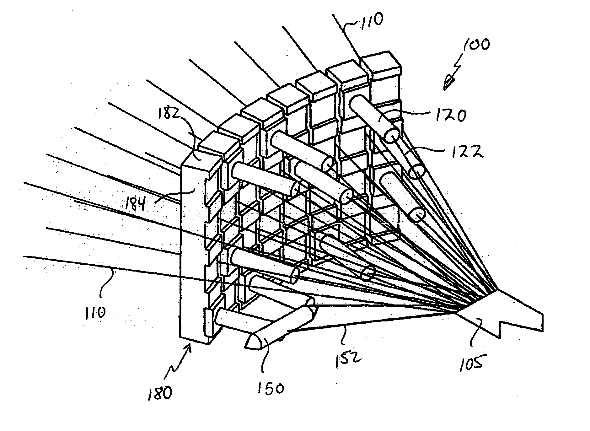
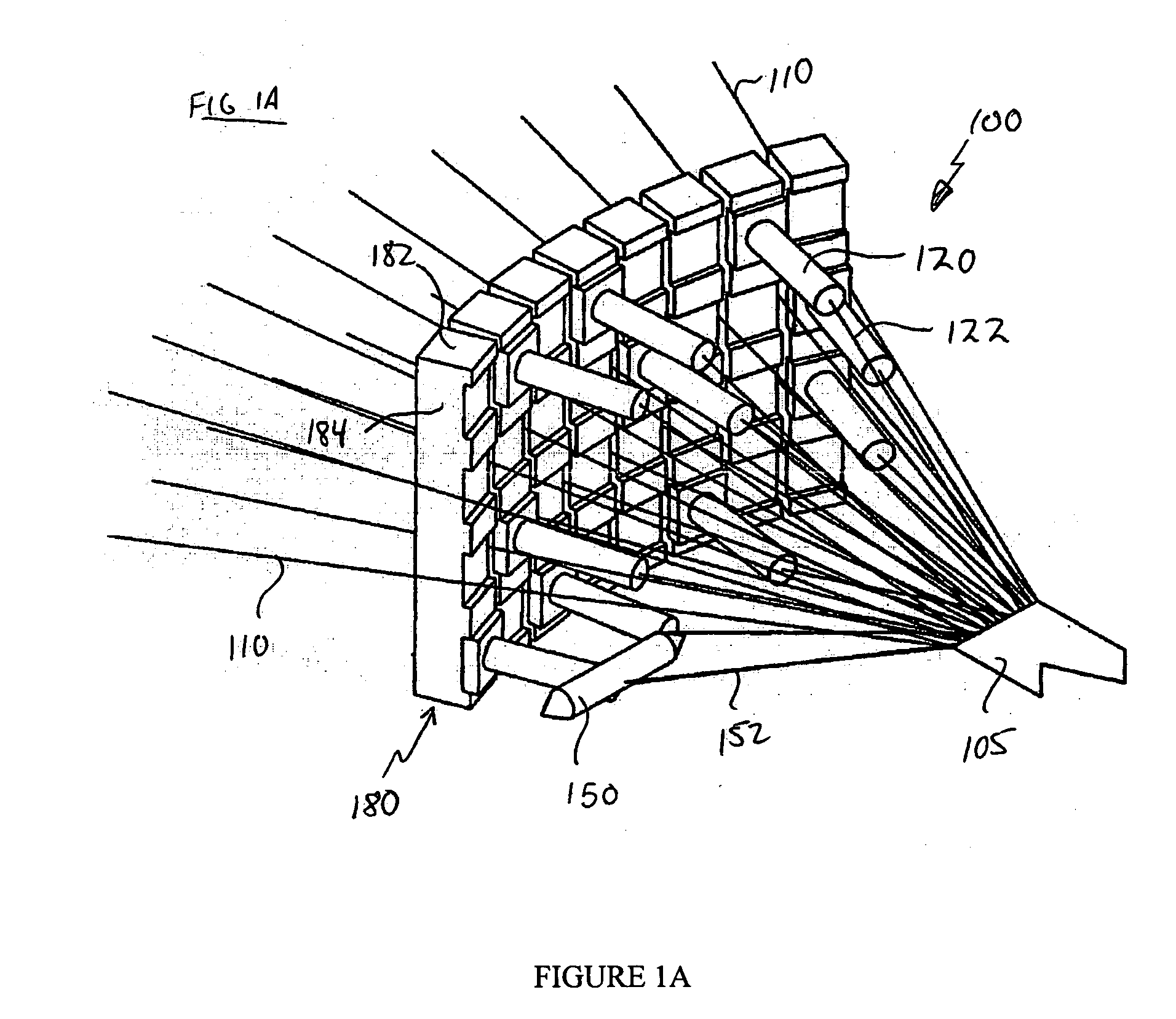
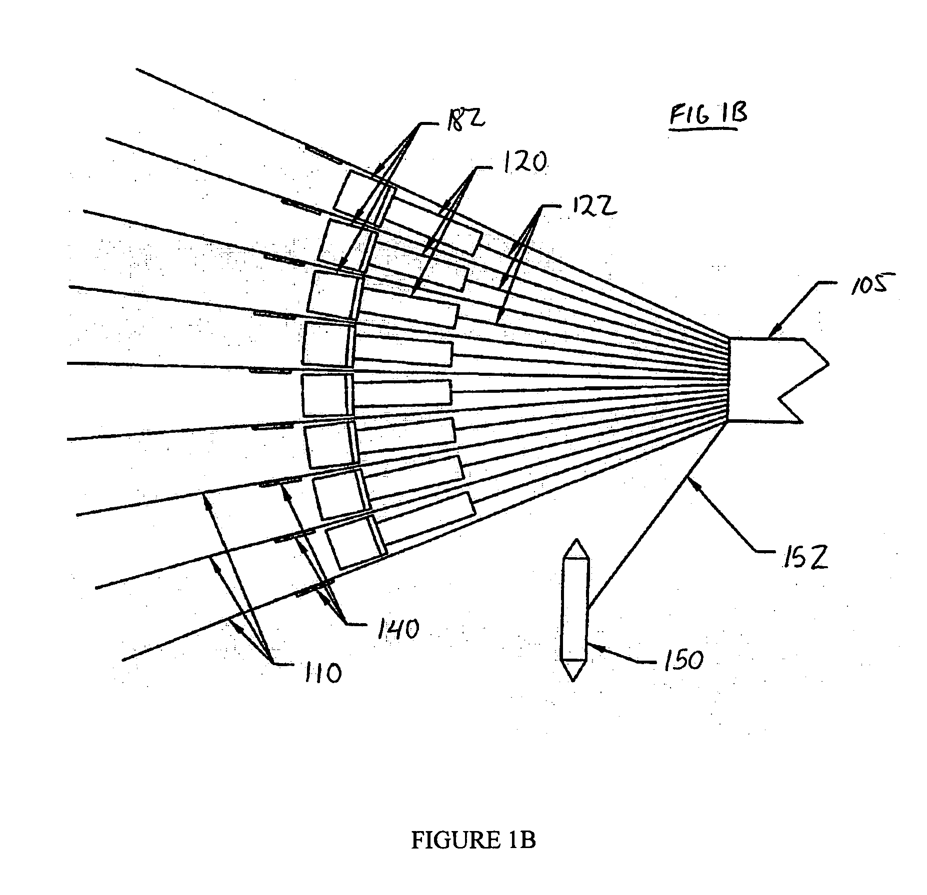
[0020] In the following detailed description, reference is made to the accompanying drawings that form a part hereof, and in which is shown by way of illustration, specific embodiments in which the invention may be practiced. These embodiments are described in sufficient detail to enable those skilled in the art to practice the invention, and it is to be understood that other embodiments may be utilized. It is also to be understood that structural, procedural and system changes may be made without departing from the spirit and scope of the present invention. The following detailed description is, therefore, not to be taken in a limiting sense, and the scope of the present invention is defined by the appended claims and their equivalents. For clarity of exposition, like features shown in the accompanying drawings are indicated with like reference numerals and similar features as shown in alternate embodiments in the drawings are indicated with similar reference numerals. Moreover, it...


PUM


Abstract

A bias-weaving machine is provided. In one embodiment, the bias-weaving machine includes a plurality of yarn carriers, each holding a yarn under tension that extends in a downstream direction towards a woven product. The yarn carriers are translatable in at least one direction other than the downstream direction. The apparatus further includes a plurality of reeds disposed to comb the yarns in a downstream direction. The reeds have a range of motion extending between positions upstream and downstream of the yarn carriers. Embodiment of this invention may advantageously be utilized to weave three-dimensional woven products, such as textile preforms for aerospace composites.

Description

RELATED APPLICATIONS [0001] This application claims the benefit of U.S. Provisional Application Ser. No. 60 / 579,474, entitled Bias Weaving Machine, filed Jun. 14, 2004.BACKGROUND [0002] 1. Technical Field [0003] This invention relates to a weaving machine, and more particularly to a bias-weaving machine suitable for forming three-dimensional woven structures. [0004] 2. Background Information [0005] The use of textile preforms is well known in the composite industry. Such preforms are commonly fabricated using relatively simple weaving machines that typically produce flat, substantially two-dimensional woven products with yarns extending in only two directions. Such materials are generally formed by interlacing two sets of yarns substantially perpendicularly to each other. In such two-dimensional weaving applications, the 0 degree yarns are referred to as warp yarns, while the 90 degree yarns are referred to as fill yarns. The introduction of bias yarns (e.g., interwoven at 45 degree...

Claims


Application Information

Patent Timeline
Patent Type & Authority Applications(United States)
IPC IPC(8): D03D41/00
CPCD03D41/004Y10S139/01
Inventor NAYFEH, SAMIR A.ROHRS, JONATHAN D.RIFAI, OSAMAHAKAMPHON, SAPPINANDANADIAZ, MAURICIOWARMAN, EMILY C.
Owner MIT
Features
  • Generate Ideas
  • Intellectual Property
  • Life Sciences
  • Materials
  • Tech Scout
  • Unparalleled Data Quality
  • Higher Quality Content
  • 60% Fewer Hallucinations
Learn More