
Compressor sound attenuation enclosure

a compressor and enclosure technology, applied in the direction of positive displacement liquid engines, instruments, liquid fuel engines, etc., can solve the problem of non-uniform thickness of the internal chamber of the shell, and achieve the effects of improving noise reduction, improving sound attenuation shell, and low cos

Inactive Publication Date: 2005-12-15
EMERSON CLIMATE TECH INC
View PDF18 Cites 37 Cited by
  • Summary
  • Abstract
  • Description
  • Claims
  • Application Information

AI Technical Summary

Benefits of technology

[0006] The present invention provides an improved sound attenuating shell for a scroll compressor that provides significantly improved noise reduction at low cost. Materials having superior sound transmission loss properties are combined with a barrier construction especially suited to provide increased absorption, and superior sound transmission loss properties.
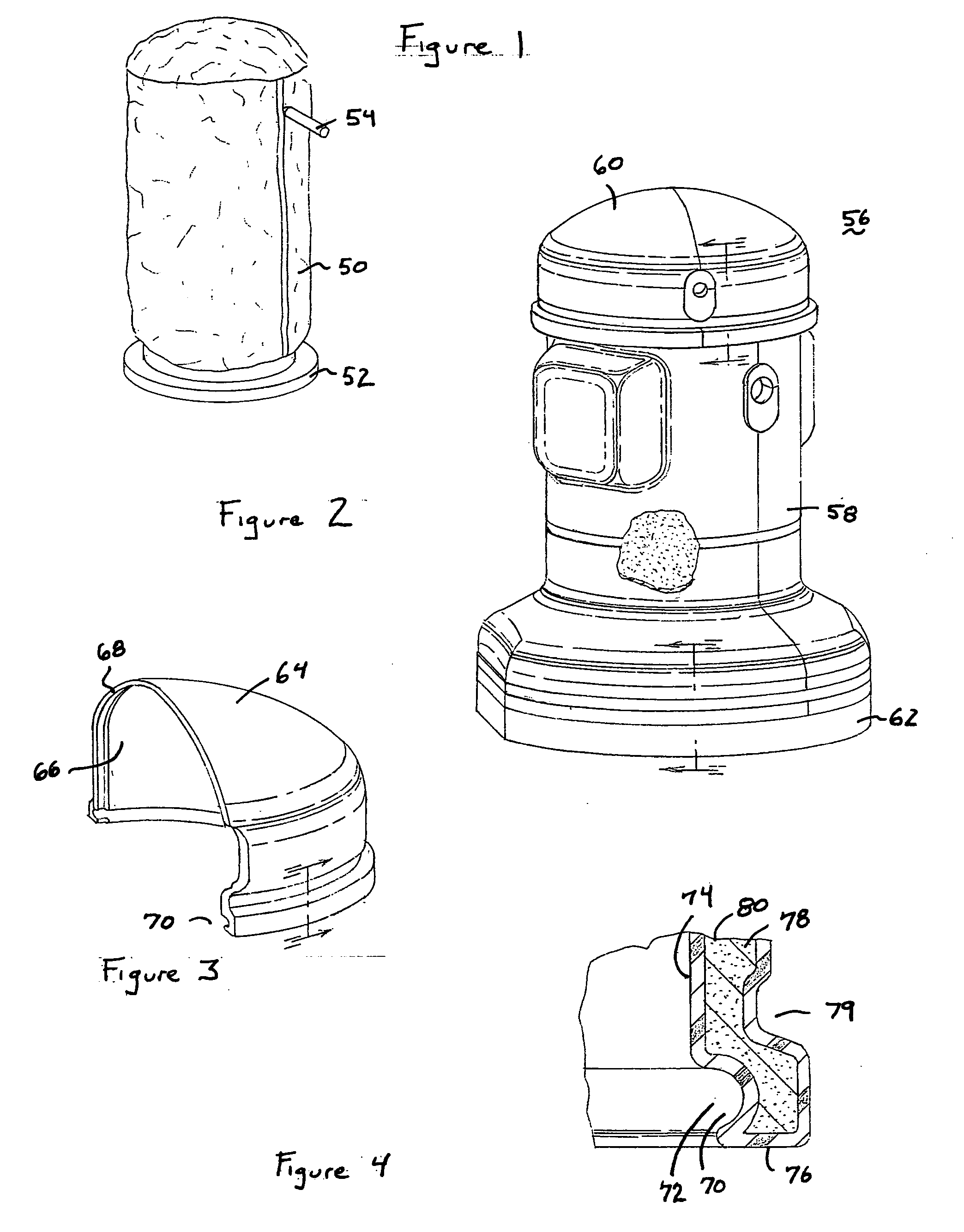
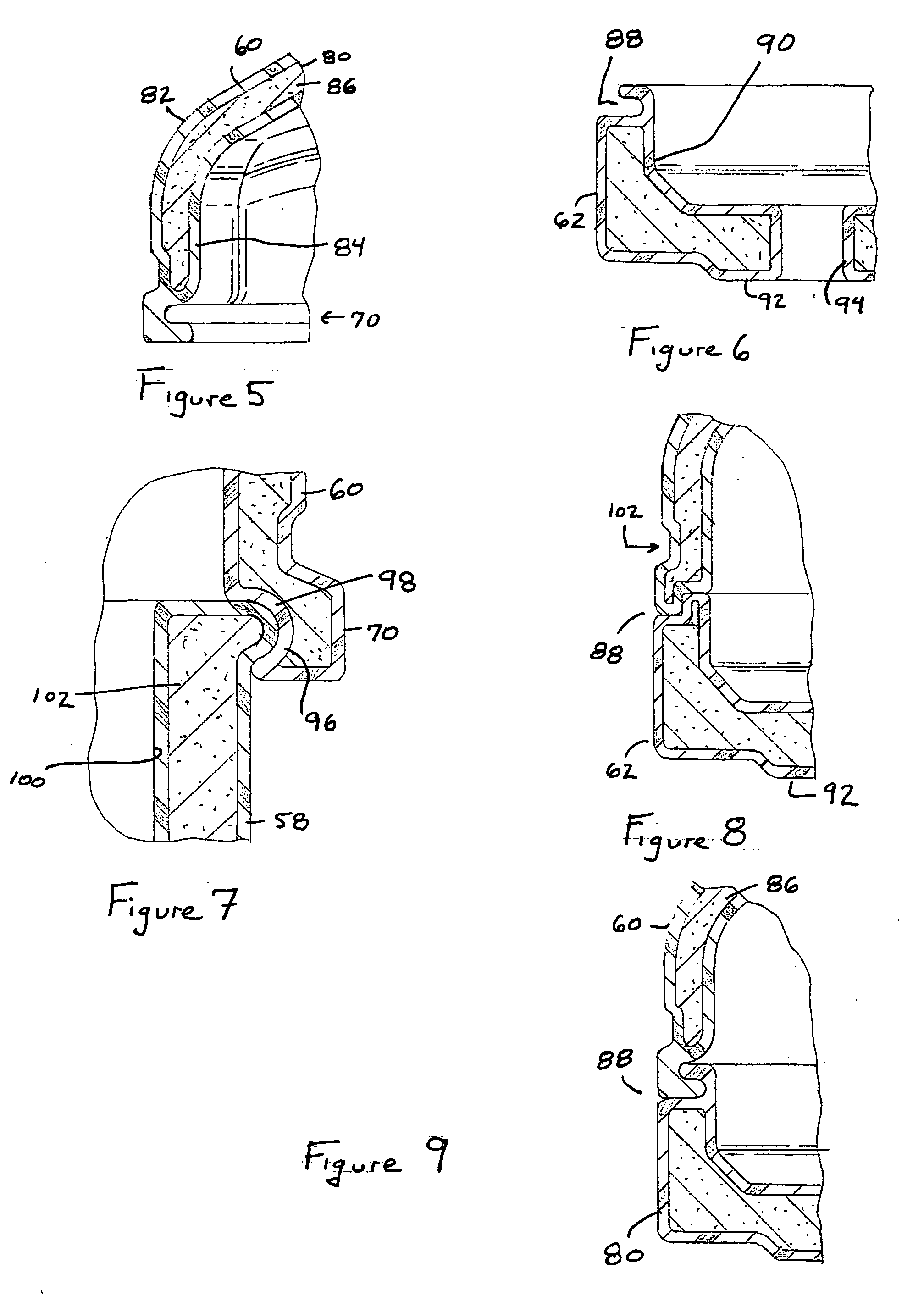
[0008] In yet another embodiment, a two layer compressor shell cover is formed of a polymer resin which defines an internal chamber. Optionally, the internal chamber of the shell has non-uniform thickness. The thickness of the internal cavity is preferably greatest over preselected areas from which emanate noise transmissions having larger amplitude, to increase noise transmission losses.
[0009] In another embodiment of the invention, a sound enclosure is provided for surrounding the shell of a compressor. The sound enclosure is vibrationally isolated from the compressor and has a mass density in lb / ft2 to reduce the transmitted noise from the compressor by greater than 10 dB.
[0010] The present invention incorporates barrier and absorption technologies in plastic constructions thereby reducing overall noise transmittance while at the same time reducing space, complexity and cost requirements of existing technologies.

Problems solved by technology

Optionally, the internal chamber of the shell has non-uniform thickness.

Method used


Image

  • Compressor sound attenuation enclosure
  • Compressor sound attenuation enclosure
  • Compressor sound attenuation enclosure

Examples


Embodiment Construction

[0029] The following description of the preferred embodiments is merely exemplary in nature and is in no way intended to limit the invention, its application, or uses. While the sound attenuating dome described is described as being associated with a compressor and more particularly a scroll compressor, it is envisioned that the teachings herein are equally applicable to other applications including but not limited to, valving, aerator assemblies, engine and motor assemblies for use in domestic, transportation, and manufacturing environments.

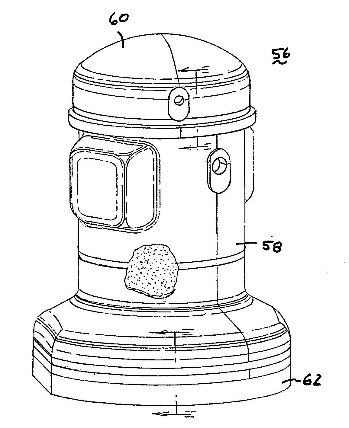
[0030]FIG. 2 represent a sound enclosure 56 having separable shell members. As can be seen, the sound enclosure 56 is formed of at least one side shell member 58, a cap shell member 60, and a base shell member 62. The sound enclosure is configured to completely surround a scroll compressor 52. Of particular significance is that the sound enclosure positions sound attenuating material at and around the base of the scroll compressor 52 to attenua...


PUM


Abstract

A sound attenuating cover for a scroll compressor is provided. The cover has a base member configured to support the compressor, the base defines a first chamber filled with a sound attenuating material. The sound attenuating chamber further has a cover member configured to cover the compressor and couple to the base, said cover member defines another chamber. This chamber is additionally filled with a sound attenuating material.

Description

CROSS-REFERENCE TO RELATED APPLICATIONS [0001] This application claims the benefit of U.S. Provisional Application No. 60 / 571,630, filed on May 14, 2004. The disclosure of the above application is incorporated herein by reference.FIELD OF THE INVENTION [0002] The present invention relates to sound enclosures and, more particularly, to sound enclosures for compressors. BACKGROUND OF THE INVENTION [0003] Continued efforts to reduce compressor weight and cost have led heating and cooling equipment manufactures to replace metal components with lighter mass materials. Often, these changes lead to increase in noise transmission from compressor units. Compressors currently sold to original equipment manufacturers are segregated into several feature categories. Significant feature categories typically considered include cost, temperature performance, aesthetics, recycling aspects and noise abatement performance. [0004] Although single frequency sound cancellation schemes have been proposed ...

Claims


Application Information

Patent Timeline
IPC IPC(8): F04D29/66F01C21/10G10K11/04F04C29/06F04B39/00F04C18/02F04B39/12F04C23/00H02K5/24
CPCF01C21/10F04B39/0033F04B39/121F04C18/02F04C23/008F04C29/066F04C2230/60F04C2240/30F04D29/664F04C29/06
Inventor SEEL, ROBERT V.
Owner EMERSON CLIMATE TECH INC
Learn More