Pad clip of disc brake apparatus

a disc brake and clip technology, applied in the field of clip, can solve the problems of difficult to employ this structure, insufficient restraint of hitting sound generation, etc., and achieve the effect of stabilizing the restraint generation of hitting sound, generating hitting sound, and reducing the difficulty of braking

Inactive Publication Date: 2005-12-15
AKEBONO BRAKE IND CO LTD
View PDF16 Cites 34 Cited by
  • Summary
  • Abstract
  • Description
  • Claims
  • Application Information

AI Technical Summary

Benefits of technology

[0015] Since, the pad clip according to the present invention is configured as described in the above, rattling of the pad with respect to the support during non-braking period is prevented, an abutting of the torque transmitting surface and the torque receiving surface with great force during braking period is prevented, and a generation of hitting sounds caused by hitting of the both surfaces with respect to each other is restrained.
[0016] In particular, in the case of the disc brake pad clip of the present invention, a force to press the backing plate of the pad in the direction of circumference of the rotor is the sum of a resilient force of the first pressing portion and a resilient force of the second abutting portion. Therefore, generation of hitting sound during braking period can be sufficiently restrained by securing these forces sufficiently.
[0017] Since the pressing portion and the second abutting portion are provided independently from each other, a force to press the backing plate of the pad by the pressing portion and the second abutting portion in the direction of the circumference of the rotor may be increased and stabilized. Therefore, the effect to restrain generation of the hitting sound is stabilized.

Problems solved by technology

Therefore, as in the case in which brake is put on relatively suddenly, when the brake torque exerted to the backing plate 6 during braking period is large, generation of hitting sound cannot be necessarily restrained satisfactorily.
Such a problem also occurs in the case of the structure described in JP-A-08-226473.
Therefore, it is difficult to employ this structure.

Method used


Image

  • Pad clip of disc brake apparatus
  • Pad clip of disc brake apparatus
  • Pad clip of disc brake apparatus

Examples


first embodiment

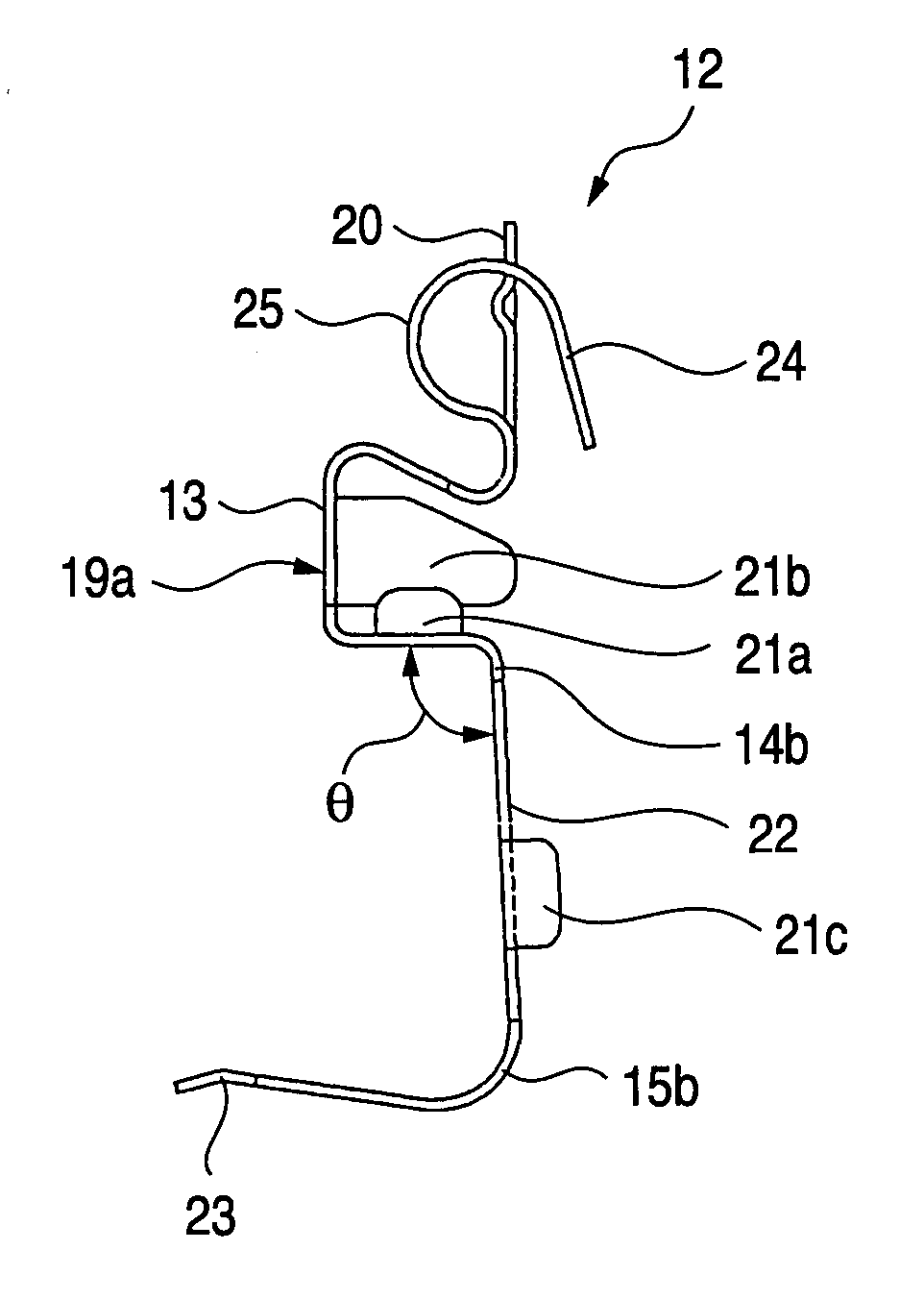
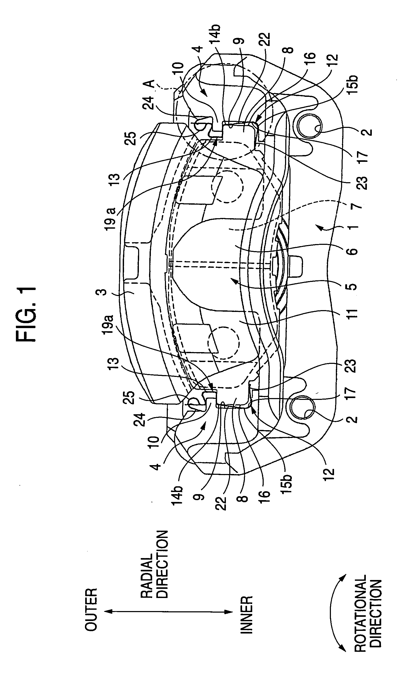
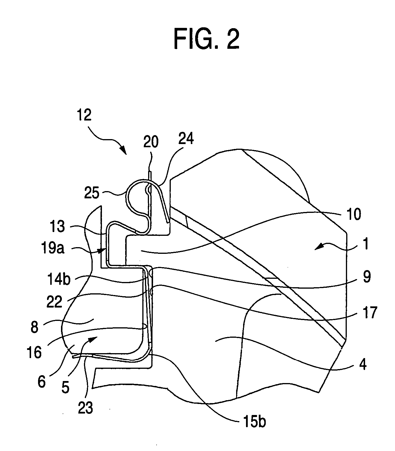
[0029] Referring now to FIG. 1 to FIG. 6, the present invention will be described. The characteristic of the present invention is in that the hitting sound generated during braking period is stably restrained by devising the shape of the pad clips 12, 12 provided between both ends of the backing plate 6 of the pad 5 and both ends of the support member 1 with respect to the rotational direction of the rotor. Since the overall structure of the disc brake apparatus to which the pad clips 12, 12 are assembled is as described above, duplicated description is omitted or simplified, and the characteristic aspects of the present invention are mainly described.

[0030] The pad clip 12 of this example is formed by bending a metallic plate having resiliency and resistance to corrosion, such as stainless steel plate. In the case of this example, the pad clip 12 is formed integrally by connecting an outer (the side of the widthwise end of the vehicle body with respect to an axial direction of the ...

second embodiment

[0039] Subsequently, FIG. 8 shows the present invention. In this embodiment, a second abutting portion 24a corresponds to an intermediate portion of a curved portion 25a formed by bending part of the metallic plate constituting a pad clip 12c, which corresponds to a portion being located radially outwardly with respect to the positioning portion 13, into an arcuate shape.

[0040] In other words, part of the metallic plate, which corresponds to the upper end of the positioning portion 13 with respect to the radial direction described above, is curved in the direction in which the radially inside and the end of the support member 1 protrude, and the proximal portion of the curved portion 25a is continued therefrom. Then, the intermediate portion of the curved portion 25a is served as the second abutting portion 24a, and the second abutting portion 24a is brought into abutment with the engaging portion 4 provided at the end of the support member 1. The structure and the effect of other p...


PUM


Abstract

A pad clip 12 is provided between a backing plate 6 and an engaging portion 4 of a support member 1 to prevent rattling of the backing plate 6 during non-braking period and generation of hitting sound during braking period. In order to restrain the hitting sound, the backing plate 6 is resiliently pressed in the rotational direction of the rotor by a pressing portion 14b and a second abutting portion 24. The above-described problem can be solved by increasing the force to press the backing plate 6 and reducing the possibility that a torque transmitting surface 16 on the backing plate 6 and a torque receiving surface 17 on the support member 1 hit against each other with great force is during braking period reduced correspondingly.

Description

BACKGROUND OF THE INVENTION [0001] The present invention relates a pad clip which is built in a disc brake apparatus of a motor vehicle and which is used to prevent rattling of a backing plate of a pad with respect to a support member during non-braking period, and to prevent the backing plate and the support member from hitting against each other with great force during braking period. [0002]FIG. 1 shows a disc brake apparatus used for braking a motor vehicle. (Note that FIG. 1 shows a disc brake apparatus in which a pad clip according to the present invention is applied, and does not show a prior art.) The disc brake apparatus is fixed to a suspension device with a support member 1 provided adjacent to one side of a rotor (not shown) rotating with a wheel with bolts (not shown) screwed into mounting holes 2, 2 formed in the support member 1 in the radially inward direction of the rotor (lower side in FIG. 1) with respect to the support member 1. The support member 1 supports a cal...

Claims


Application Information

Patent Timeline
Patent Type & Authority Applications(United States)
IPC IPC(8): F16D65/40F16D65/097
CPCF16D65/0972F16D65/0977
Inventor NOGIWA, JUNICHI
Owner AKEBONO BRAKE IND CO LTD
Why Eureka
Try Eureka