
Electroless plating method

a technology of electroless plating and plating substrate, which is applied in the direction of non-metallic protective coating application, liquid/solution decomposition chemical coating, coating, etc., can solve the problems of reducing the production yield of wiring substrate and bringing about the reduction of production yield

Inactive Publication Date: 2004-10-28
SHINKO ELECTRIC IND CO LTD
View PDF12 Cites 3 Cited by
  • Summary
  • Abstract
  • Description
  • Claims
  • Application Information

AI Technical Summary

Benefits of technology

[0013] The present invention is created to prevent the electric short-circuit between the conductive patterns caused by applying the plating to space portions between the conductive patterns, when the metal layer is formed selectively on the conductive patterns formed on the insulating body by the electroless plating.
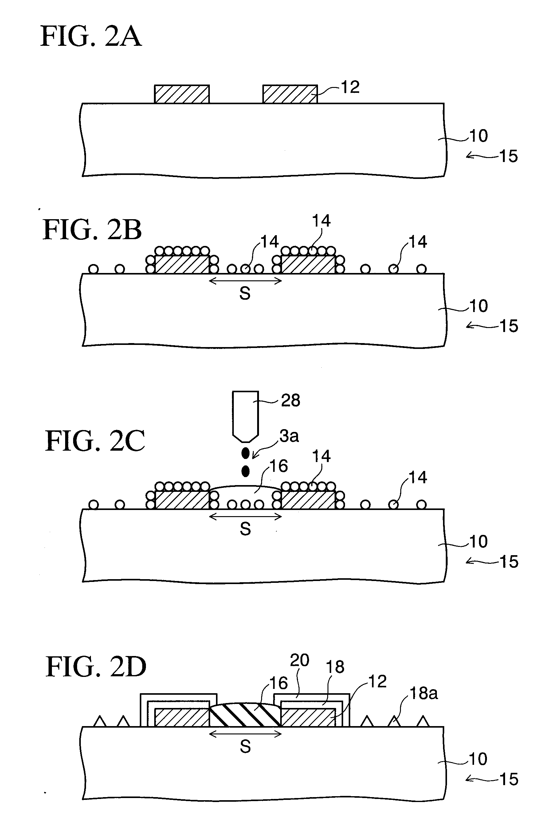
[0015] When doing this, the catalytic metal is not exposed or the catalytic metal becomes inactive, in the space portions between the conductive patterns. Therefore, the electroless plating is not applied to the space portions between the conductive patterns. As a result, generation of the mutual electric short-circuit between the patterns can be prevented even in the fine conductive patterns.
[0018] Therefore, the protection film (or the oxidizing agent) can be formed in a very short time. As a result, the electric short-circuit between the conductive patterns can be prevented at a low cost, and thus production yield of the wiring substrate can be improved.
[0021] If doing this, the electroless plating is applied selectively only to the conductive patterns because the catalytic metal does not exist in the space portions between the conductive patterns. Thus, generation of the electric short-circuit between the conductive patterns can be prevented.

Problems solved by technology

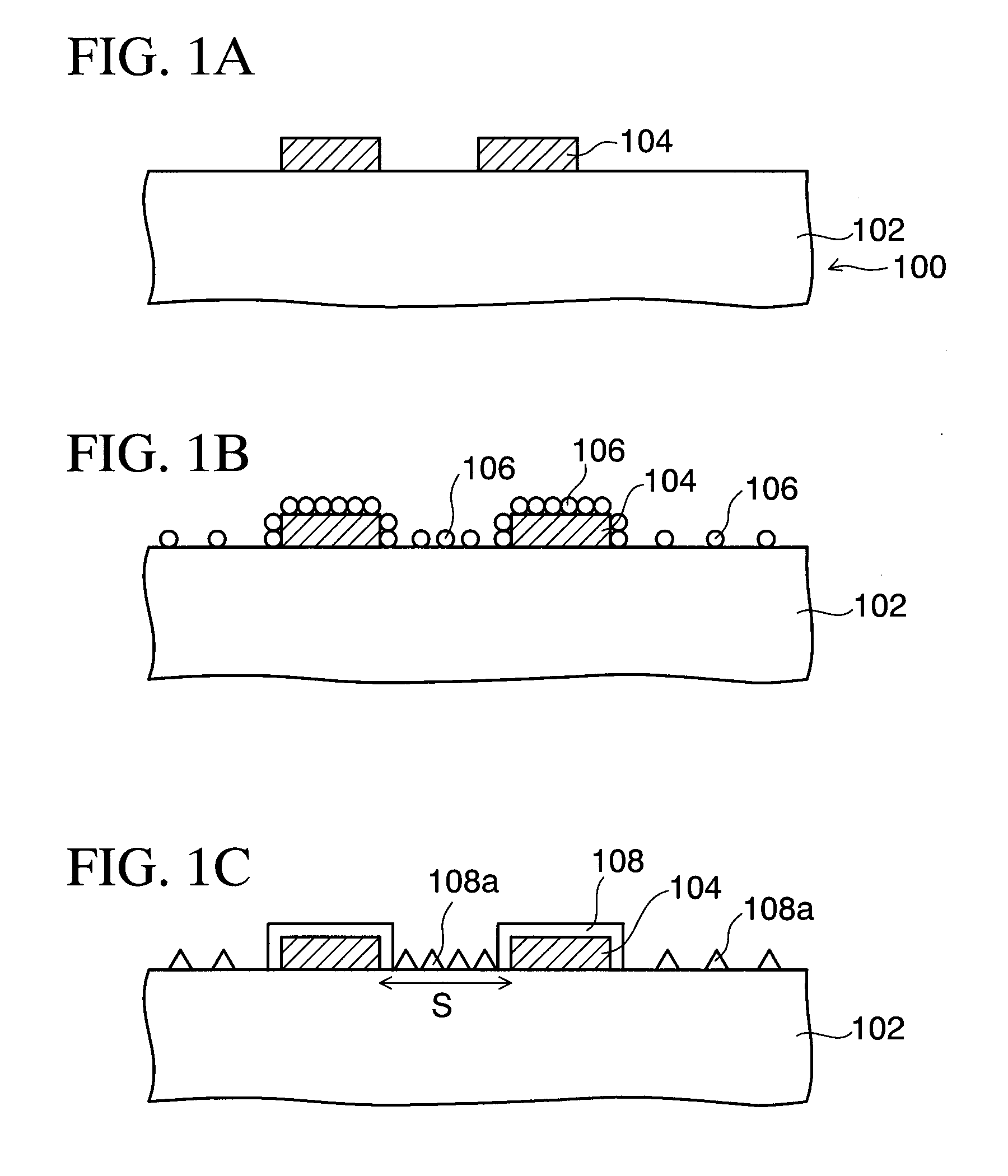
However, because palladium is attached onto the insulating body, such insulating body is slightly plated.
Therefore, such problems existed that the copper electrodes are ready to short-circuit electrically particularly in portions in which space portions between the copper electrodes are narrow, and thus production yield of the wiring substrate is lowered.
Thus, such a problem existed that a reduction in yield of the production is brought about.

Method used


Image

  • Electroless plating method
  • Electroless plating method
  • Electroless plating method

Examples


second embodiment

[0060] FIGS. 3A to 3D are sectional views showing an electroless plating method of a second embodiment of the present invention. A difference of the second embodiment from the first embodiment is that Pd is adhered selectively to Cu electrodes only. Detailed explanation of the similar steps to those in the first embodiment will be omitted herein.

[0061] In the electroless plating method of the second embodiment of the present invention, as shown in FIG. 3A, like the first embodiment, first the substrate 15 having the structure in which the Cu electrodes 12 are formed on the insulating body 10 is prepared. Then, the substrate 15 is cleaned with ethanol, and then is dipped into the 50% hydrochloric acid (HCl) solution to apply the soft etching to surfaces of the substrate 15. Then, the substrate 15 is dipped into the tin chloride (II)(SnCl.sub.2) solution to adhere the Sn (II) ions onto the substrate 15.

[0062] Then, as shown in FIG. 3B, the coating liquid 3a formed of the palladium chl...


PUM

PropertyMeasurementUnit
Electrical conductoraaaaaaaaaa

Abstract

An electroless plating method of the present invention includes the steps of preparing a substrate having an insulating body and a conductive pattern formed thereon, adhering a catalytic metal serving as a catalyst of an electroless plating onto the insulating body and the conductive pattern, forming selectively a protection film or an oxidizing agent used to oxidize the catalytic metal on the catalytic metal in a space portion between the conductive pattern, and forming selectively a metal layer on the conductive pattern by the electroless plating.

Description

[0001] 1. Field of the Invention[0002] The present invention relates to an electroless plating method and, more particularly, an electroless plating method that is applicable in the step of plating selectively a metal layer on conductive patterns.[0003] 2. Description of the Related Art[0004] In the related art, in the steps of manufacturing the wiring substrate, etc., there is the step of forming selectively the gold layer on conductive patterns by the electroless plating. For example, in the wiring substrate on which electronic parts are packaged, normally electrodes are formed of copper. Thus, in many cases the metal layer such as the nickel layer, the gold layer, or the like is formed selectively on the copper electrodes to enhance reliability of the connection to the electronic parts.[0005] In such wiring substrate, the solder resist film having opening portions on the copper electrodes, surfaces of which are subjected to the catalytic activating process, is formed. Then, the m...

Claims


Application Information

Patent Timeline
IPC IPC(8): C23C18/30C23C18/16C23C18/28H05K3/18H05K3/24H05K3/28
CPCH05K3/244H05K2201/0761H05K2201/09881H05K2203/013H05K2203/0716H05K2203/072H05K2203/0796C23C18/1635C23C18/1889C23C18/1605C23C18/1608C23C18/1651C23C18/208C23C18/285C23C18/30C23C18/36
Inventor MURAYAMA, KEI
Owner SHINKO ELECTRIC IND CO LTD
Learn More