Device for high-precision generation and measurement of forces and displacements

a technology of force and displacement, which is applied in the direction of force/torque/work measurement apparatus, mechanical control devices, instruments, etc., can solve the problems of poor signal/noise ratio for small signals, inability to meet sufficiently large paths and forces, and accuracy and reproducibility of force transfer. achieve the effect of greater forces and displacemen

Active Publication Date: 2009-06-09
ZWICK
View PDF23 Cites 3 Cited by
  • Summary
  • Abstract
  • Description
  • Claims
  • Application Information

AI Technical Summary

Benefits of technology

[0014]One object of the invention is to provide a device for high-precision generation and measurement of forces and displacements, which has a high rigidity perpendicular to the axis in which the forces and displacements are being generated. Such a device according to an embodiment of the invention has a relatively simple structure, and provides great reliability and reproducibility of the forces and displacements being generated and measured.
[0024]One advantage of a device according to an embodiment of the invention is that forces and displacements in one direction (for example, an X direction) are reliably generated and, at the same time, measured, by means of leaf springs that are clamped in on both sides and biased in a longitudinal (Y) direction. Embodiments of the invention can be used for high-precision generation and measurement of very small forces, and also for greater forces and displacements. Furthermore, a plurality of devices according to embodiments of the invention can be combined such that forces and displacements can be generated and measured in several directions.
[0025]Because the generation and measurement of the forces and displacements are conducted mechanically, the device is not susceptible to electromagnetic interference, and the substrate holders do not have to be electrically insulating.
[0026]A further advantage of a device according to an embodiment of the invention is that the device is very rigid in a direction perpendicular to the generated force / displacement (in the Y direction) because of the bias of the leaf springs, so that no displacement that acts in this perpendicular direction occurs, i.e. a force that acts in this direction cannot result in a displacement.

Problems solved by technology

Such methods, however, are only suitable for sufficiently large paths and forces.
In this system, however, the bearings can influence the accuracy and reproducibility of the force transfer.
Elongation measurement strips, however, have a poor signal / noise ratio for small signals.
However, the forces that can be generated are on the order of 10 mN, and this is a significant disadvantage.
Furthermore, the work is carried out using voltages of more than 100 V, which presents the risk of electric blowout.
This would cause the force generation to become unusable.
Here, a disadvantage is the low rigidity in a direction perpendicular to the force and displacement being generated.
In the case of the three solutions described above; however, a defined bias force of the membrane springs or leaf springs is not adjustable, and thereby each of the systems demonstrates insufficient rigidity.

Method used


Image

  • Device for high-precision generation and measurement of forces and displacements
  • Device for high-precision generation and measurement of forces and displacements
  • Device for high-precision generation and measurement of forces and displacements

Examples


Embodiment Construction

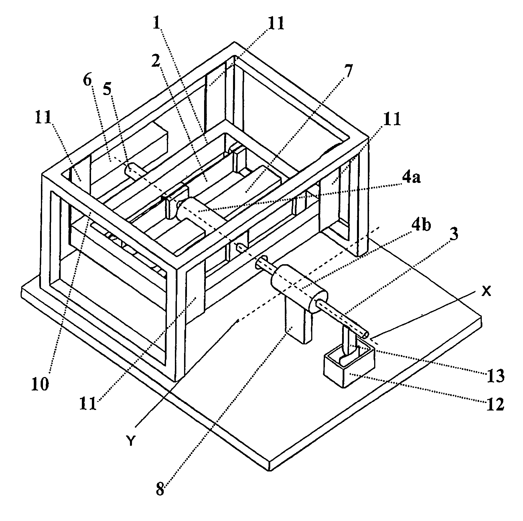
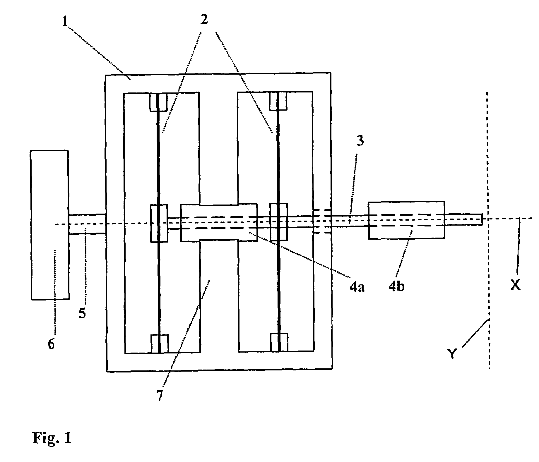
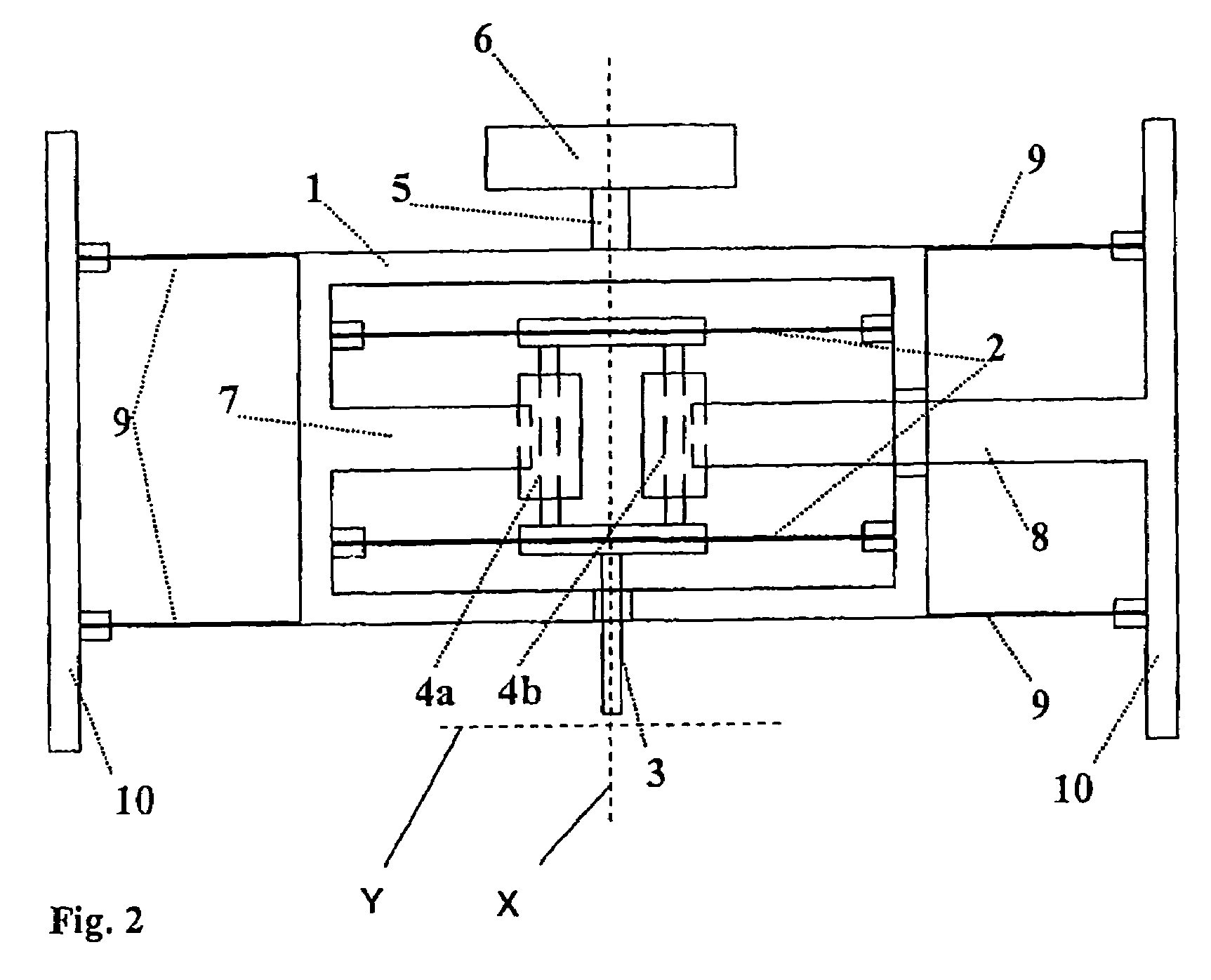
[0036]The principle of the invention may be explained in greater detail with reference to FIG. 1. At least one double pair of leaf springs 2 is attached at their short ends, in a rigid, closed frame 1, and tensed in a vertical direction. Leaf springs 2 are rigidly connected with a force-transferring shaft 3, in the direction of which (X axis) the generation of force and / or displacement occurs (both pressure and tension).

[0037]Two ferrite cores of LVDTs 4a, 4b are rigidly attached to the force-transferring shaft 3. One LVDT 4a is for measuring force and is connected with the closed frame 1 with a rigid holder 7. A second LVDT 4b is rigidly connected with an external reference body, which serves as a reference point for the measurement of the displacement of the shaft 3.

[0038]Frame 1 may be connected with a movement element, such as a piezoelectric element 6, by way of a connecting shaft 5. The movement element can move the frame 1 back and forth in the longitudinal direction along th...


PUM


Abstract

A device for high precision generation and measurement of forces (both pressure and tension) and displacements along a single axis includes a shaft for transferring the forces along an axis X. At least two biased first leaf springs are attached to the shaft and clamped at each end. The device has great rigidity in an axis Y perpendicular to the axis X in which the forces and displacements are generated.

Description

CROSS REFERENCE TO RELATED APPLICATIONS[0001]Applicants claim priority under 35 U.S.C. §119 of GERMAN Application No. 10 2005 003 830.1 filed on Jan. 25, 2005.BACKGROUND OF THE INVENTION[0002]1. Field of the Invention[0003]The invention relates to a device for high-precision generation and measurement of forces and displacements.[0004]2. Description of the Prior Art[0005]High-precision generation and measurement of forces and displacements along an axis are generally used in the production of nano-indenters and scratch or wear testers. Forces and displacements in such devices are generated in different ways, according to the state of the art, whereby as a rule, only great rigidity of the moved shaft in the movement direction is a matter of concern.[0006]Force and / or displacement can be generated and / or measured electrically (for example, electrostatically or capacitatively), magnetically, mechanically, or by means of a combination of the aforementioned methods. Simple methods for de...

Claims


Application Information

Patent Timeline
Patent Type & Authority Patents(United States)
IPC IPC(8): G05G11/00
CPCG01N3/42G01N3/46G01N2203/0035G01N2203/0051Y10T74/20354G01N2203/0623Y10T74/20006Y10T74/20372G01N2203/0286
Inventor CHUDOBA, THOMASLINSS, VOLKER
Owner ZWICK
Why Eureka
Try Eureka