
Discharge lamp having a cathode with carbon solid-solved in a tungsten metal substrate of the cathode

a technology of carbon solid solution and discharge lamp, which is applied in the direction of gas discharge lamp details, electric discharge tubes, electrical apparatus, etc., can solve the problems of lanthanum (la) evaporated and dried out, stable discharge cannot be maintained, and the reduction of lanthanum oxide (lasub), so as to achieve accelerated reduction reaction, long life, and generation of flicker

Inactive Publication Date: 2010-06-24
USHIO DENKI KK
View PDF4 Cites 4 Cited by
  • Summary
  • Abstract
  • Description
  • Claims
  • Application Information

AI Technical Summary

Benefits of technology

[0008]The present invention has been accomplished for the purpose of solving the problems mentioned above, and the object is to provide a discharge lamp having a cathode containing lanthanum oxide (La2O3) as an electron emission material, wherein reduction of the lanthanum oxide (La2O3) is accelerated and the supply quantity of lanthanum (La) is increased, and the lamp has a long lifespan.
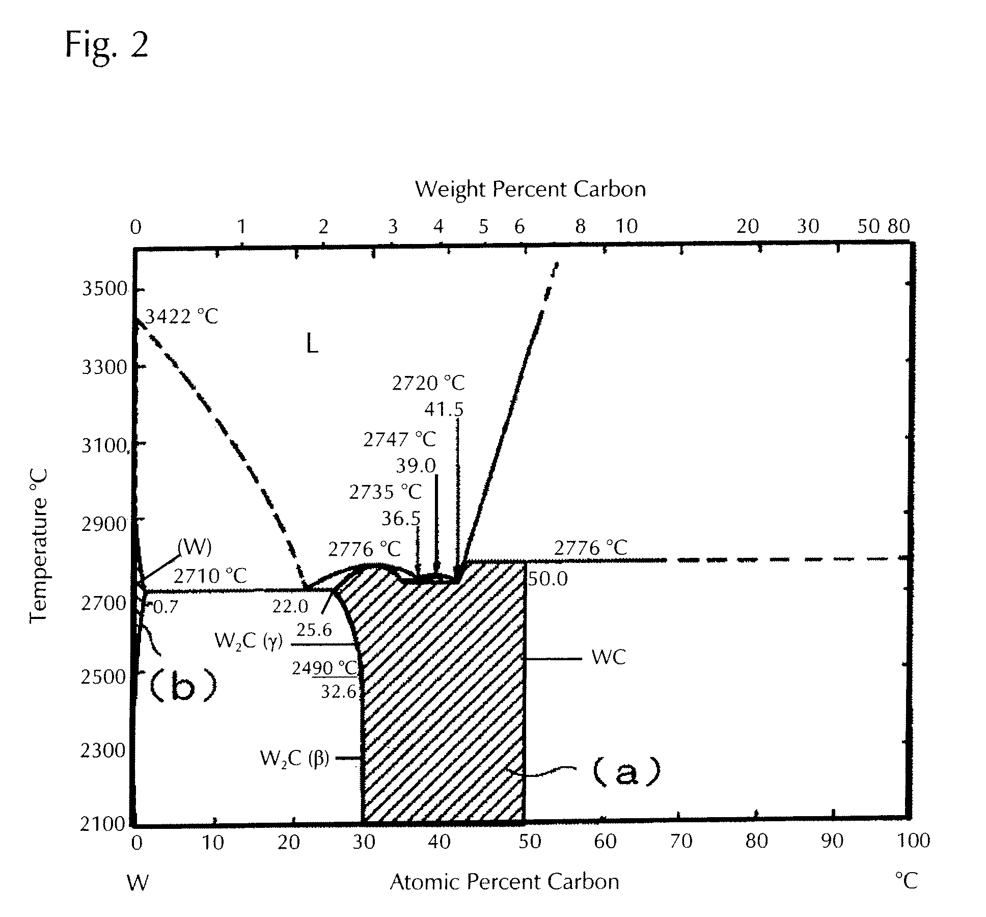
[0011]According to the discharge lamp relating to the first aspect of the present invention, the reduction of lanthanum oxide (La2O3) proceeds even at a site where the temperature does not comparatively become higher at the time of operating the discharge lamp and lanthanum (La) can be generated by incorporating carbon (C) as a solid solution into the cathode containing lanthanum oxide (La2O3) as an electron emission material. Compared to the case where no carbon (C) is solid-solved into the cathode, the portion which is the supply source of lanthanum (La) can be expanded, and the supply quantity of lanthanum (La) is increased, and thus, a discharge lamp with a long lifespan can be provided.
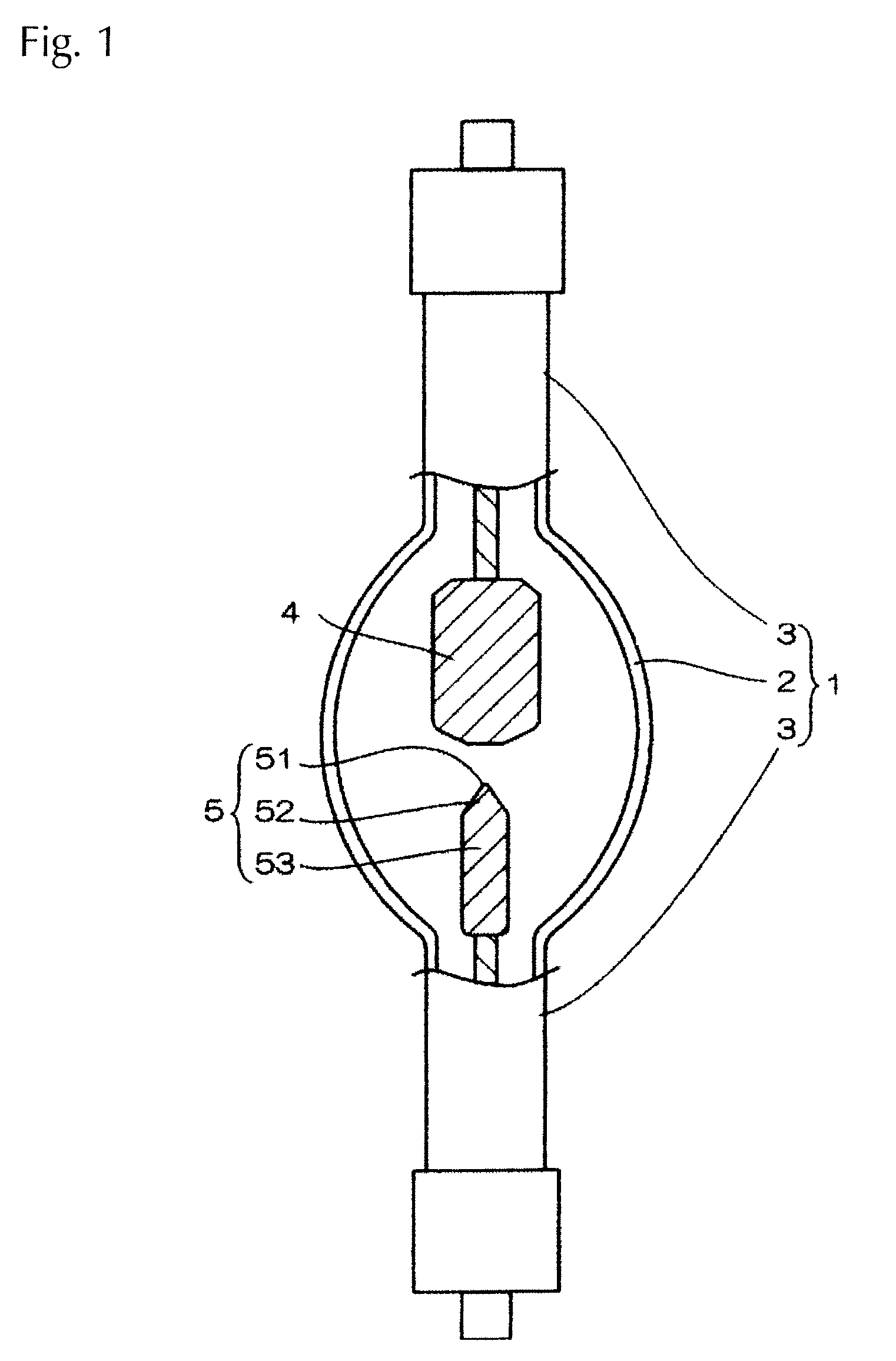
[0012]According to the discharge lamp relating to the second aspect of the present invention, a reduction reaction can be inhibited by increasing the concentration of carbon (C) at the tip part of the cathode, which reaches a high temperature at the time of operation, to increase the CO partial pressure in the vicinity of lanthanum oxide particles, and an outflow of lanthanum (La) is prevented and consumption at the tip part of the cathode can be inhibited. Further, since the temperature of the taper part in the cathode does not become so high even at the time of operation, the concentration of carbon (C) is decreased as compared to the tip part and the reduction reaction is accelerated. Lanthanum (La) generated at the taper part is diffused along the grain boundary of tungsten (W), and generation of flickering due to lack of lanthanum (La) is prevented. Preferably, the concentration of the solid-solver carbon at the tip part approximately 3 mm away from the surface is in the range of 20 to 100 wt.ppm and the concentration of the solid-solved carbon at the taper part approximately at least 3 mm away from the surface is in the range of 5 to 20 wt.ppm.

Problems solved by technology

However, in the discharge lamp having a cathode containing lanthanum oxide (La2O3) as an electron emission material, there is the problem that lanthanum (La) evaporates and is dried out in an early stage because of the high-temperature load applied to the cathode at the time of operation, and stable discharge can no longer be maintained.
Although the evaporation and drying out of lanthanum (La) in an early stage can be prevented by mixing it with at least one type of metal oxide selected from zirconium (Zr) and hafnium (Hf), reduction of the electron emission material contained as lanthanum oxide (La2O3) to lanthanum is insufficient, and lanthanum (La) is still insufficient for the purpose of providing a discharge lamp with a long lifespan.
When the amount of lanthanum (La) is insufficient, there are problems that the coverage factor of lanthanum (La) atoms (surface density of La atoms regarded as 1 at the time of coating with a mono-atomic layer) becomes smaller at the tip part of the cathode, and the work function becomes great and the cathode temperature is increased and the cathode becomes deformed, and flickering occurs.

Method used


Image

  • Discharge lamp having a cathode with carbon solid-solved in a tungsten metal substrate of the cathode
  • Discharge lamp having a cathode with carbon solid-solved in a tungsten metal substrate of the cathode
  • Discharge lamp having a cathode with carbon solid-solved in a tungsten metal substrate of the cathode

Examples


experimental example

[0052]A xenon short arc lamp was manufactured using a cathode where carbon is solid-solved in a material containing a metal oxide of lanthanum and a metal oxide of zirconium in a tungsten metallic substrate, and the lamp pressure was measured at the time of operation up to 1,000 hours.

[0053]The configurations of the cathode and the xenon short arc lamp are as follows:

[0054]Enclosed gas: xenon (Xe) 0.65 MPa (static pressure)

[0055]Input: 2 kW

[0056]Cathode: axial length: 15 mm, external diameter of barrel part: 6 mm, angle of taper part: 40°, main component: tungsten, 2 wt. % of La2Zr2O7 added

[0057]As Experimental Object 1, a cathode made of a material where carbon with a concentration of approximately 10 wt.ppm was solid-solved into tungsten was prepared. As Experimental Object 2, a cathode made of a material with carbon solid-solved into tungsten having a carbon concentration at the tip part approximately 3 mm away from the surface of approximately 50 wt.ppm and a carbon concentratio...


PUM

PropertyMeasurementUnit
wavelengthaaaaaaaaaa
dielectric breakdownaaaaaaaaaa

Abstract

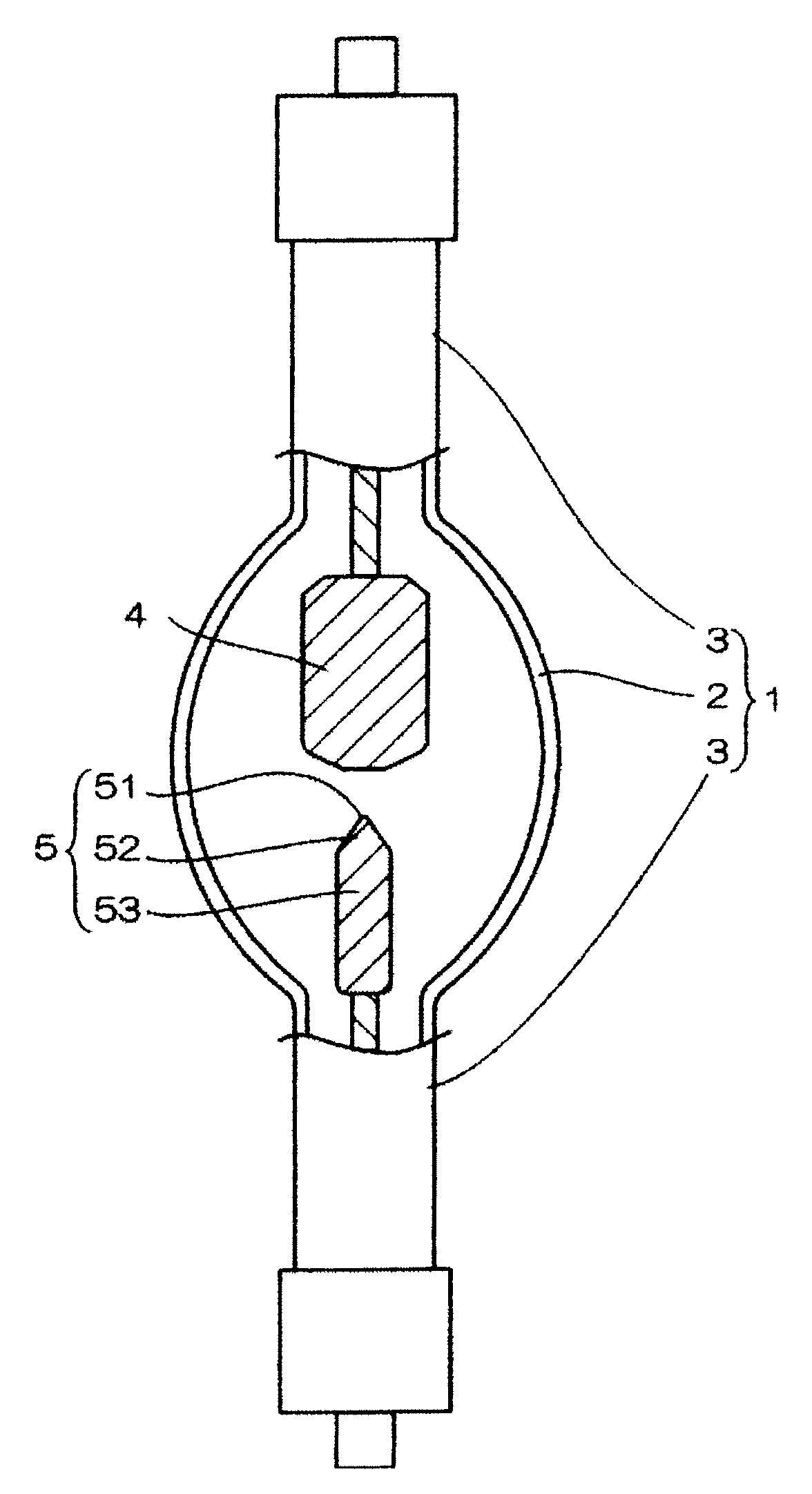
A discharge lamp having a cathode containing lanthanum oxide (La2O3) as an electron emission material, to provide a discharge lamp where reduction of lanthanum oxide (La2O3) is accelerated; a supply amount of lanthanum (La); and its lifespan is long has an anode (4) and a cathode (5) arranged within a discharge vessel (1) so as to face toward each other in a tube axis direction of the discharge vessel (1), and the cathode (5) is made from a material containing a metal oxide of lanthanum (La2O3) and a metal oxide of zirconium (ZrO2) in a tungsten metal (W) substrate with carbon present as a solid solution in the tungsten metal (W) substrate forming the cathode (5).

Description

BACKGROUND OF THE INVENTION[0001]1. Field of Invention[0002]The present invention relates to a discharge lamp with a high load and high radiance, and relates to a discharge lamp using a material containing lanthanum (La) in the cathode material as an electron emission material.[0003]2. Description of Related Art[0004]In a discharge lamp where mercury is enclosed in the discharge space used as a light source for an exposure device used for an exposure process or a discharge lamp where xenon gas is enclosed in the discharge space used as a light source in a film projector, it is known that excellent electron emission characteristics can be obtained by incorporating lanthanum oxide (La2O3) as an electron emission material in a cathode consisting primary of tungsten (W). However, in the discharge lamp having a cathode containing lanthanum oxide (La2O3) as an electron emission material, there is the problem that lanthanum (La) evaporates and is dried out in an early stage because of the ...

Claims


Application Information

Patent Timeline
Patent Type & Authority Applications(United States)
IPC IPC(8): H01J61/06
CPCH01J61/0737H01J61/06
Inventor IKEUCHI, MITSURUARIMOTO, TOMOYOSHI
Owner USHIO DENKI KK
Learn More