Eureka AIR delivers breakthrough ideas for toughest innovation challenges, trusted by R&D personnel around the world.

Compact production of reformate and segregated H2, N2 and CO2

a technology of segregation and reformate, which is applied in the direction of chemistry apparatus and processes, oxygen/ozone/oxide/hydroxide, and unvaporized water entering the shift, etc., can solve the problems of loss of some hydrogen, damage to the shift catalyst therein, and unvaporized water draining into the shift, etc., to achieve segregation and hydrogen generation, reduce space, and low cost

Active Publication Date: 2009-08-18
INT FUEL CELLS
View PDF12 Cites 3 Cited by
  • Summary
  • Abstract
  • Description
  • Claims
  • Application Information

AI Technical Summary

Benefits of technology

[0011]Objects of the invention include provision of a compact fuel processing system for generating hydrogen-containing reformate in reduced space; generation of segregated hydrogen, nitrogen and carbon dioxide efficiently and at low cost; generating high pressure pure hydrogen in an efficient manner; generating hydrogen, nitrogen and carbon dioxide in a compact fuel processing apparatus; improved generation of hydrogen-containing reformate with less than 10 parts per million of carbon monoxide; and avoiding hydrogen waste which occurs with other hydrogen processing systems, such as pressure swing adsorption systems.
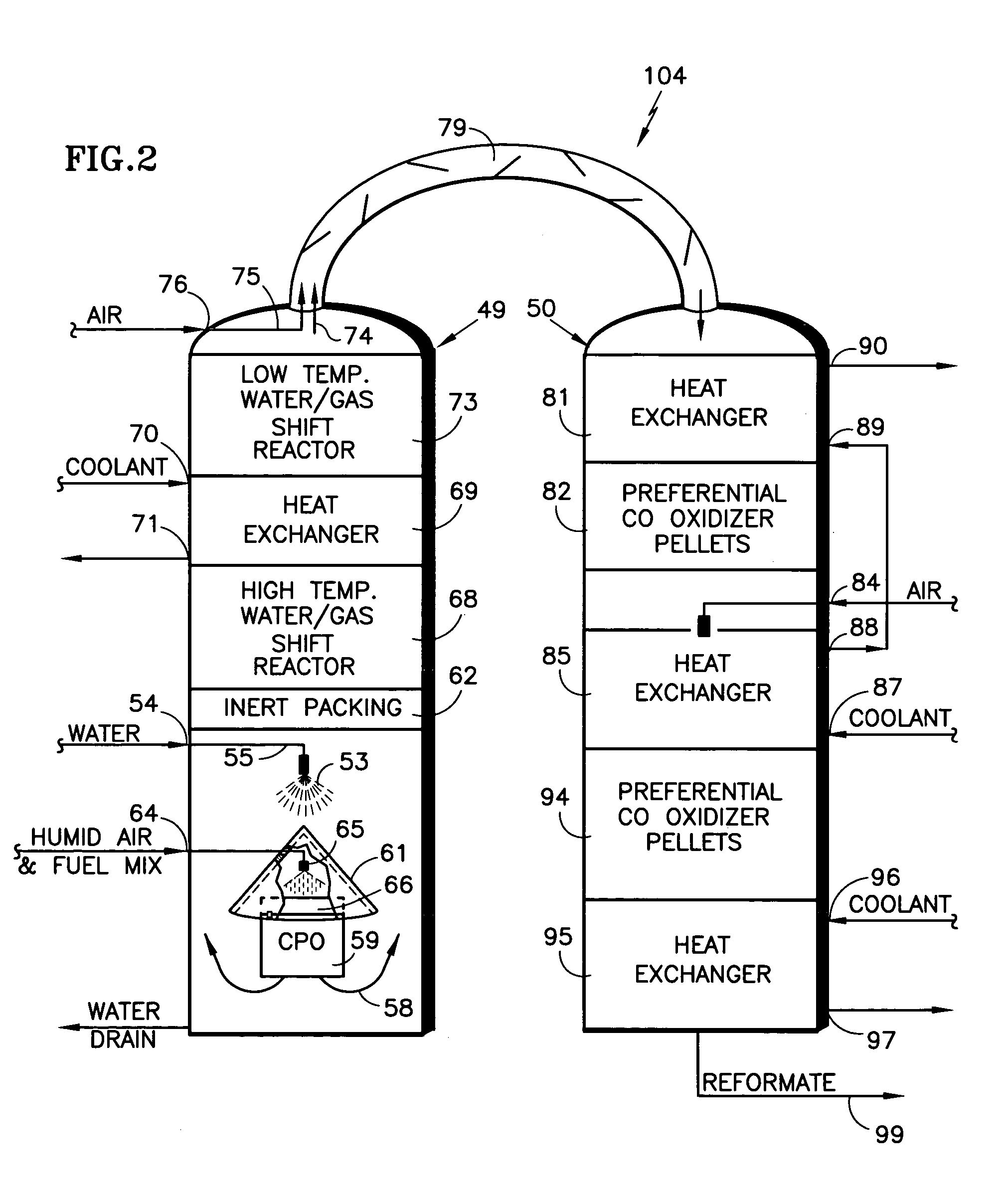
[0012]According to the present invention, a fuel processing system utilizes an up-flow reformer tower in which the water is introduced downwardly, in counterflow with the output of a generator of hydrogen-rich gas, such as a catalytic partial oxidizer, thereby providing superior mix of the water and hydrogen / CO mixture; the up flow design results in complete vaporization of the water before reaching the water / gas shift reactors, which allows use of smaller catalytic packages by as much as one-third, thereby significantly reducing the pressure across the reformer tower; because there is greater evaporation and the up flow design includes protection for the CPO, more water may be injected into the process, thereby ending up with less carbon monoxide in the output of the fuel processing system.
[0013]According further to the invention, a down-flow preferential CO oxidizer tower includes at least one bed of loose pellets having a preferential carbon monoxide oxidizer catalyst therein, which is inexpensive, easily catalysized, and presents more surface area to the gas therein.
[0014]In accordance with the invention, a fuel processing system making reformate from which pure hydrogen is to be provided separates inlet air into substantially pure oxygen and nitrogen, utilizing oxygen instead of air to feed the CPO and the preferential carbon monoxide oxidizers in the fuel processing system results in pure hydrogen having no nitrogen therein; this aspect of the invention significantly reduces the volume of gas flowing through the system and allows it to be made very compact. The invention therefore provides pure nitrogen for any segregated use; the invention requires no steam in the hydrocarbon feed stock which renders the fuel processing system not only inexpensive, but also very easy to operate.

Problems solved by technology

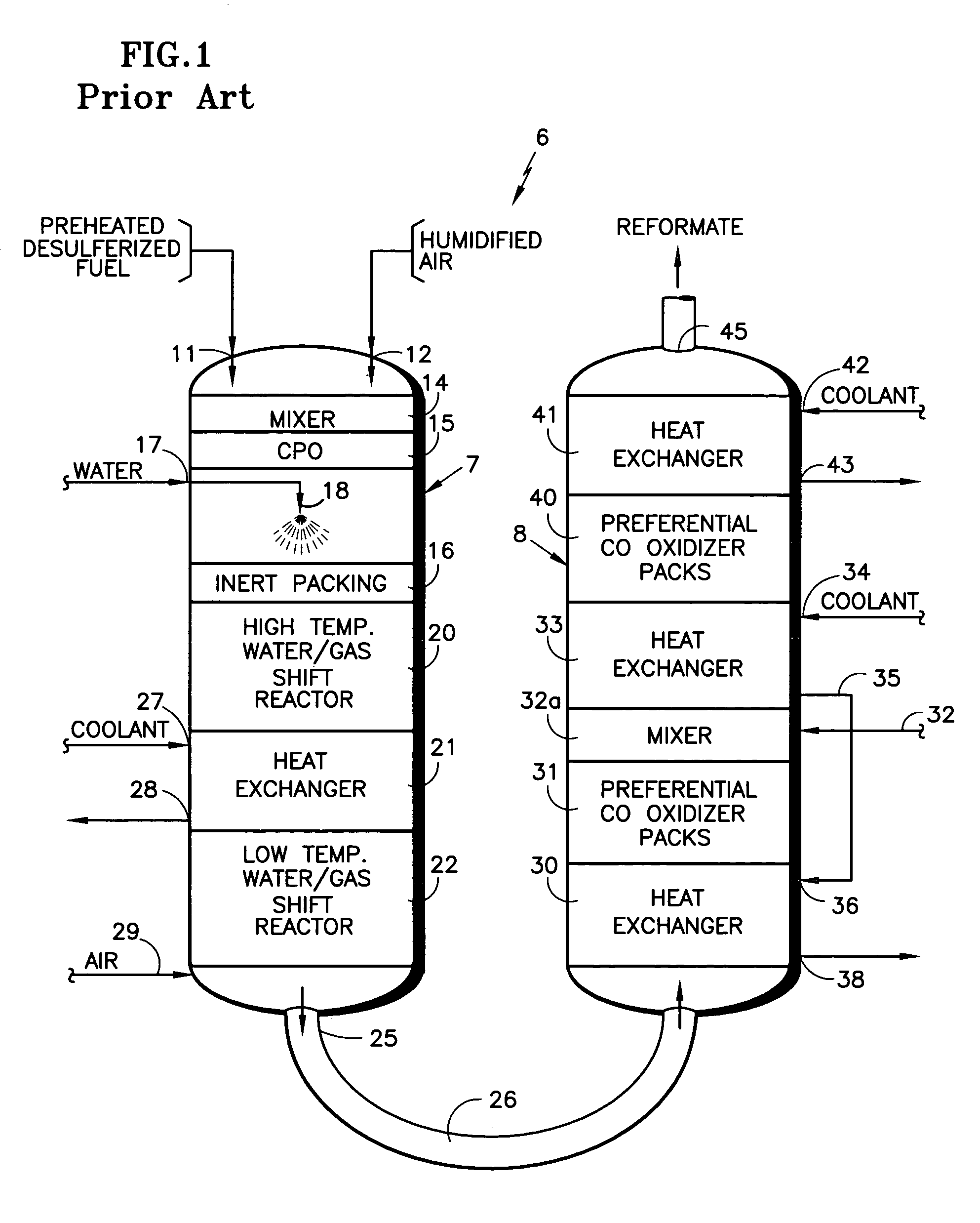
Problems with the apparatus described with respect to FIG. 1 include insufficient residence time for water droplets in the inert packing 16 to become fully vaporized; un-vaporized water may drain into the shift reactor 20 and damage the shift catalyst therein.
In the production of hydrogen, it has heretofore been known to generate reformate, as described hereinbefore, and separate the hydrogen by means of a pressure swing adsorption system, as shown in U.S. Pat. Nos. 5,961,928 and 6,051,192, which results in a loss of some of the hydrogen during purges, and therefore reduces the efficiency of the process.

Method used


Image

  • Compact production of reformate and segregated H2, N2 and CO2
  • Compact production of reformate and segregated H2, N2 and CO2
  • Compact production of reformate and segregated H2, N2 and CO2

Examples


Embodiment Construction

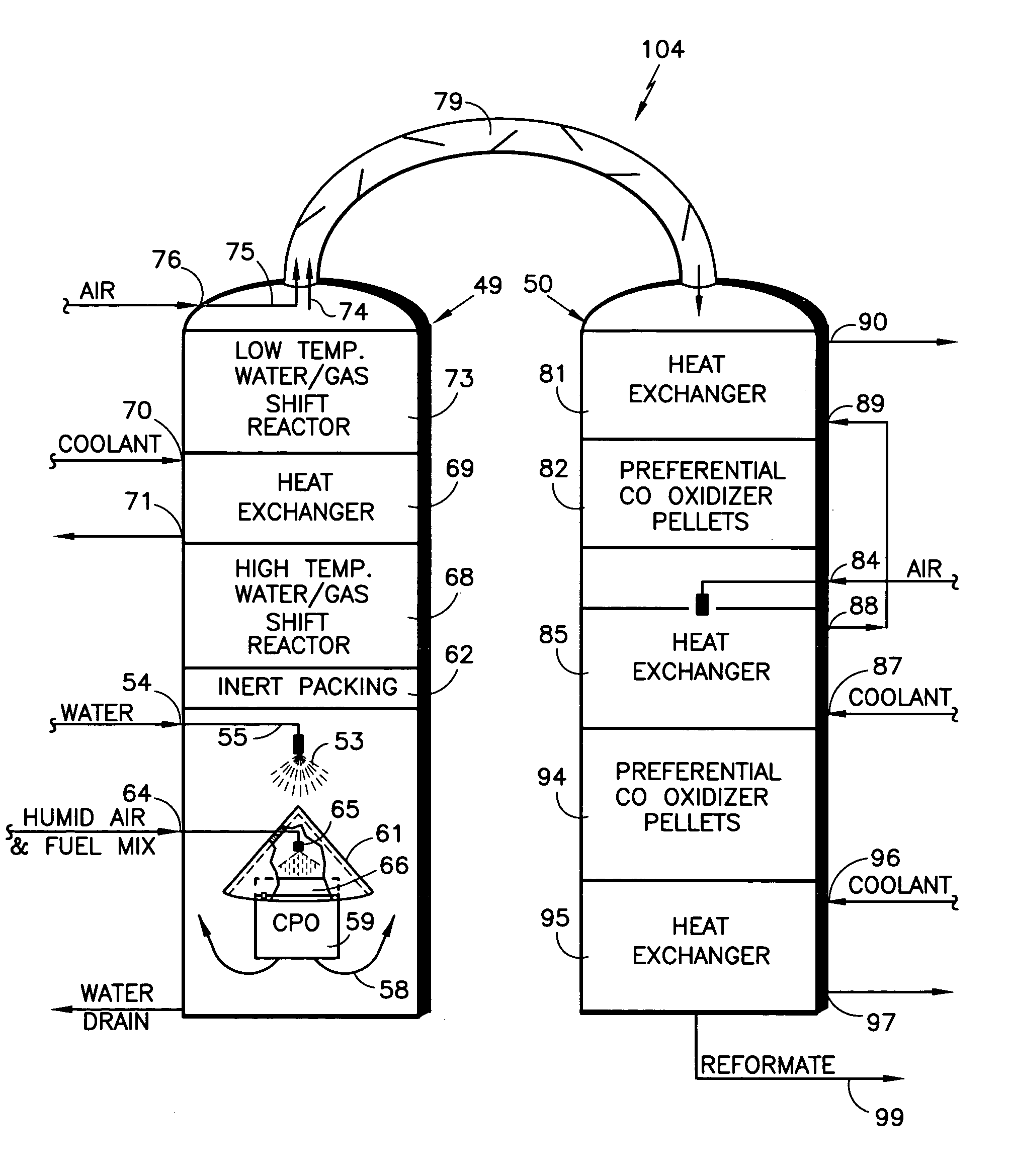
[0020]Referring to FIG. 2, a fuel processing system 104 for generating hydrogen-rich reformate, in accordance with the present invention, includes an up-flow reformer and water / gas shift reactor tower 49 and a down-flow preferential carbon monoxide oxidizer (PrOx) tower 50. A major difference between the fuel processing system 48 and those known to the prior art is that the flow of water droplets 53 formed with water from an inlet 54 by a nozzle 55 is counter to the flow of the hot, output 58 of the CPO 59. The CPO 59 is protected from the water by a shield 61. This causes both complete mixing as well as complete vaporization of the water droplets before reaching the hot, inert packing 62. Furthermore, since the water is sprayed downwardly, and is in counter flow with the CPO output 58, there is a greater residence time of water droplets, especially the bigger water droplets, to assist mixing and full vaporization of even the larger water droplets before reaching the inert packing 6...


PUM

PropertyMeasurementUnit
pressureaaaaaaaaaa
pressureaaaaaaaaaa
temperatureaaaaaaaaaa

Abstract

Substantially pure oxygen is provided to an up flow reformer (49a) from a separator (108) downwardly impelled water droplets (53) mix with the outflow (58) of a CPO (59), flowing upwardly through high temperature (68) and low temperature (73) water gas shift reactors. The reformer output flows through a mixer (79) to a down-flow PrOx containing two beds (82, 94) of preferential CO oxidation catalyst therein. A series of compressors (120-122) compress water and carbon dioxide out of the gaseous flow to provide pure, pressurized hydrogen. Oxygen (111) is separated (105, 108) from nitrogen (112).

Description

TECHNICAL FIELD[0001]This invention relates to efficient and compact production of (1) hydrogen-containing reformate, as well as (2) segregated pure high pressure hydrogen, such as may be used for fueling stations, (3) nitrogen and (4) carbon dioxide.BACKGROUND ART[0002]The generation of hydrogen-containing reformate from hydrocarbon fuels, for various purposes such as regeneration of adsorbents used to trap oxides of nitrogen in the exhaust of internal combustion engines, particularly diesel engines, is accomplished in various ways. In a typical system, hydrocarbon fuel is desulfurized and preheated, mixed with air, and passed through some form of reformer, typically a catalytic partial oxidizer, a non-catalytic homogenous partial oxidizer, an auto-thermal reformer, and the like. If reformate is to be utilized, for instance, as fuel for a fuel cell power plant, which produces electricity from hydrogen and oxygen (typically air), the carbon monoxide in the hydrogen-rich gas must be ...

Claims


Application Information

Patent Timeline
Patent Type & Authority Patents(United States)
IPC IPC(8): B01J7/00B01J8/00B01J8/04C01B3/38C01B3/48C01B13/02
CPCB01J8/0453B01J8/0492B01J8/0496C01B3/386C01B3/48C01B13/0259B01J8/0457C01B2210/0046B01J2208/00168B01J2208/00522B01J2208/00849B01J2208/025B01J2219/00006B01J2219/0004C01B2203/0261C01B2203/0288C01B2203/044C01B2203/047C01B2203/146
Inventor LIU, KEROHRBACH, ERIC A.
Owner INT FUEL CELLS
Why Eureka
Eureka Blog
Learn More