Display device and driving method thereof

a technology of a display device and a driving method, which is applied in the direction of electric digital data processing, instruments, computing, etc., can solve the problems of increasing the thickness and weight of the display device, many errors in photo sensing responsive to touch, and inability to display detailed characters or pictures. , to achieve the effect of accurate responsiveness to user touch

Inactive Publication Date: 2005-12-15
SAMSUNG DISPLAY CO LTD
View PDF9 Cites 116 Cited by
  • Summary
  • Abstract
  • Description
  • Claims
  • Application Information

AI Technical Summary

Benefits of technology

[0009] An object of the present invention is to provide a display device and a driving method thereof capable of generating a stable output signal of a photosensor in order to determine touch information accurately responsive to user touch regardless of variation of external circumstances.

Problems solved by technology

However, such a separate touch panel increases a thickness and weight of the LCD device and makes it hard to display detailed characters or pictures.
However, such a photosensor causes many errors in photo sensing responsive to touch since an output characteristic of the photosensor is varied depending on ambient circumstances, i.e., an intensity of external light, a luminance of a backlight, temperature, and so on.

Method used


Image

  • Display device and driving method thereof
  • Display device and driving method thereof
  • Display device and driving method thereof

Examples


Embodiment Construction

[0027] The present invention now will be described more fully hereinafter with reference to the accompanying drawings, in which exemplary embodiments of the invention are shown. This invention may, however, be embodied in many different forms and should not be construed as limited to the embodiments set forth herein.

[0028] In the drawings, the thickness of layers and regions are exaggerated for clarity. Like numerals refer to like elements throughout. It will be understood that when an element such as a layer, film, region, substrate or panel is referred to as being “on” another element, it can be directly on the other element or intervening elements may also be present. In contrast, when an element is referred to as being “directly on” another element, there are no intervening elements present.

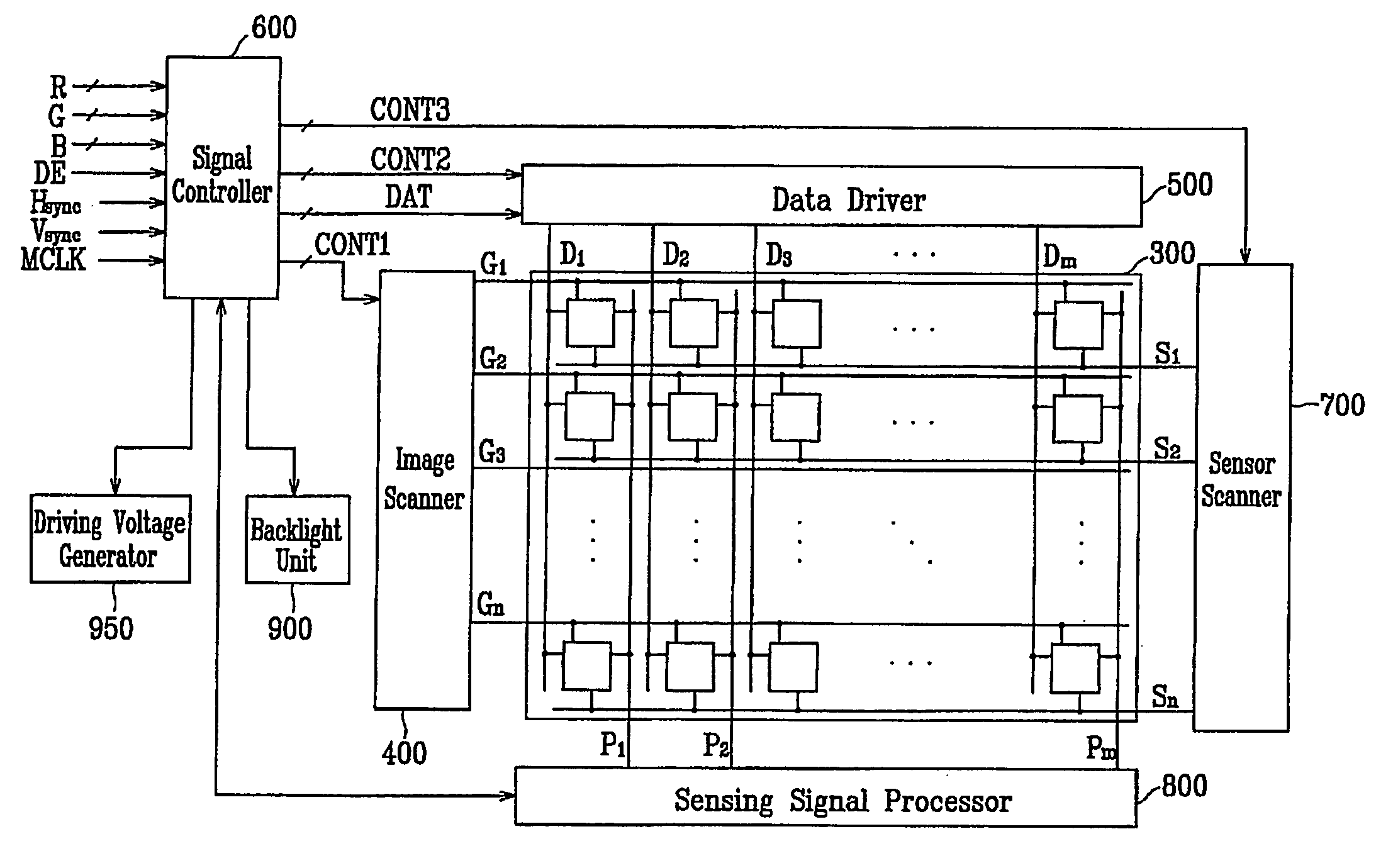
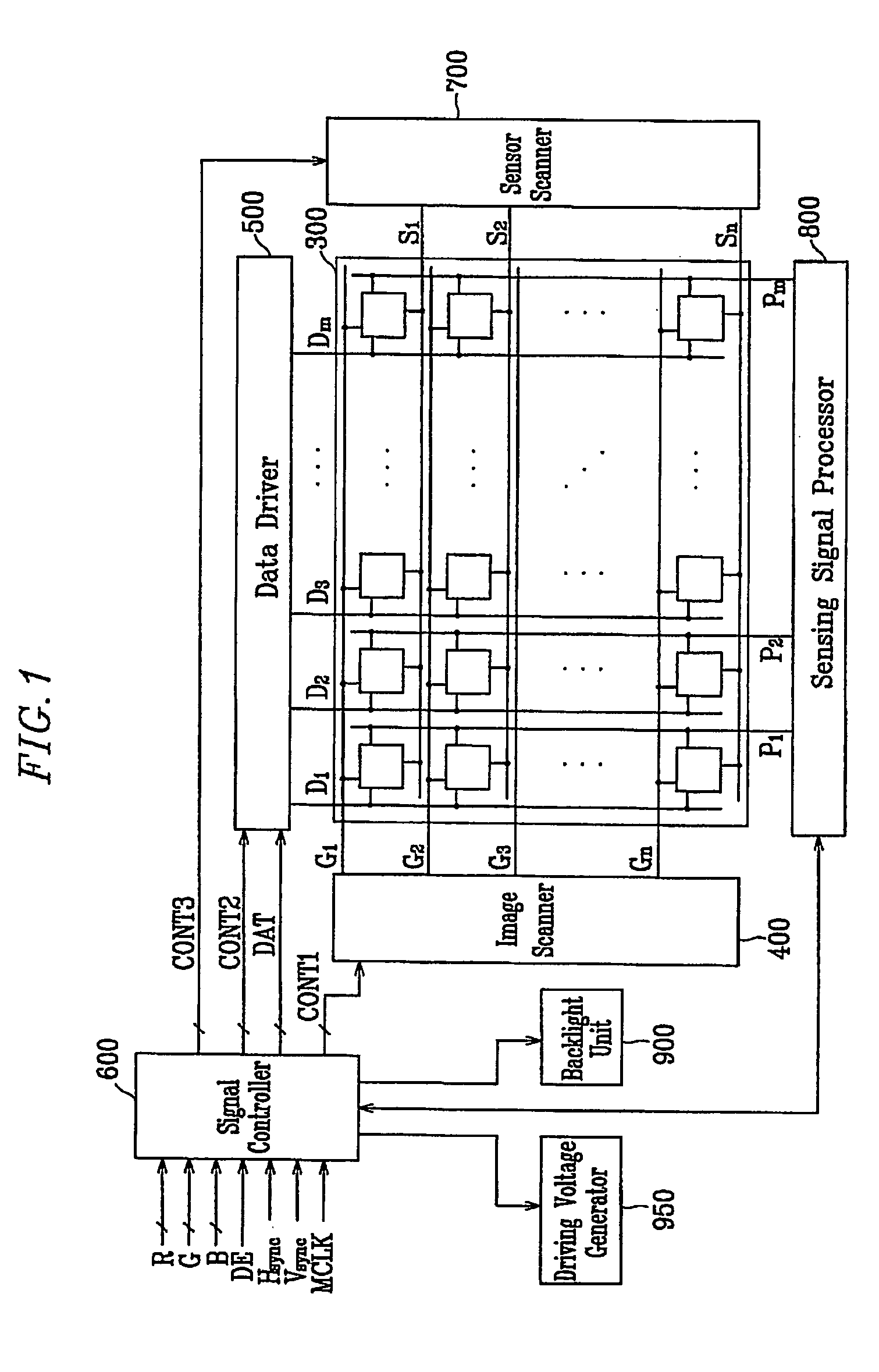
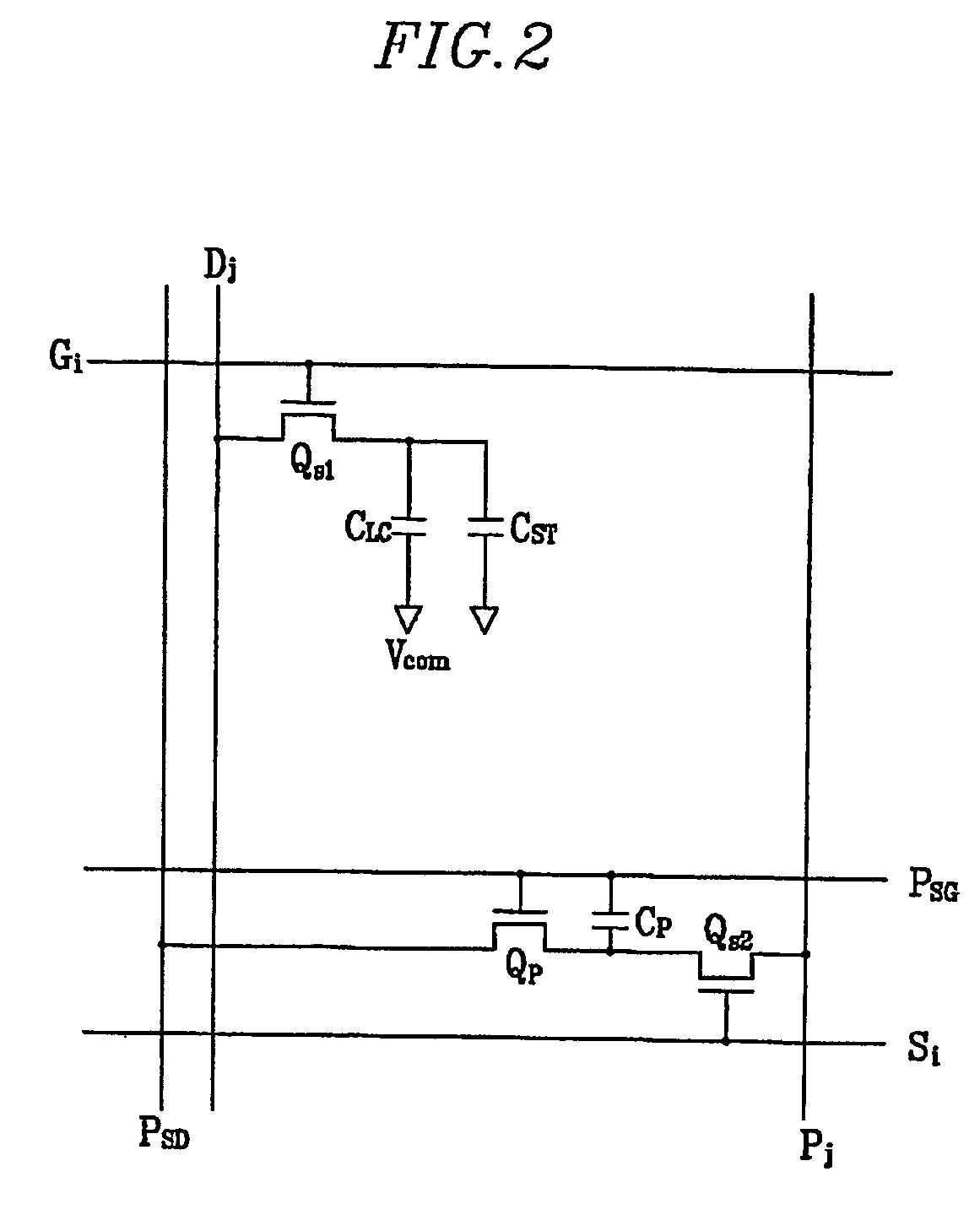
[0029]FIG. 1 is a block diagram of a liquid crystal display (LCD) device according to an exemplary embodiment of the present invention, and FIG. 2 is an equivalent circuit diagram of a pixe...


PUM

PropertyMeasurementUnit
inclination angleaaaaaaaaaa
inclination anglesaaaaaaaaaa

Abstract

A display device includes a panel assembly, a backlight unit supplying light to the panel assembly, a first photosensor, a second photosensor, a sensing signal processor and a signal controller. The first photosensor is supplied with ambient light and light from the backlight unit to generate a first sensing signal. The second photosensor is blocked from the ambient light and receives the light from the backlight unit to generate a second sensing signal. The sensing signal processor receives the first and the second sensing signals from the first and the second photosensors for processing. The signal controller determines a sensing state responsive to processed first and second sensing signals from the sensing signal processor and performing a predetermined control operation responsive to the sensing state.

Description

[0001] This application claims priority to Korean Patent Application Nos. 2004-0042574 filed on Jun. 10, 2004, and 2004-0064038 filed on Aug. 13, 2004, and all the benefits accruing therefrom under 35 U.S.C §119, and the contents of which in their entirety are herein incorporated by reference. BACKGROUND OF THE INVENTION [0002] (a) Field of the Invention [0003] The present invention relates to a display device and a driving method thereof. [0004] (b) Description of Related Art [0005] A typical liquid crystal display (LCD) device includes a lower panel and an upper panel and a liquid crystal (LC) layer with dielectric anisotropy disposed between the lower and upper panels. The lower and upper panels are provided with pixel electrodes and a common electrode. The pixel electrodes are arranged in a matrix and each pixel electrode is connected to a switching element Q such as a thin film transistor (TFT). Each row of pixel electrodes is sequentially supplied with data voltages. The commo...

Claims


Application Information

Patent Timeline
Patent Type & Authority Applications(United States)
IPC IPC(8): G06F3/033G02F1/133G06F3/041G06F3/042G09G3/20G09G3/34G09G3/36
CPCG06F3/0412G06F3/0421
Inventor PARK, JONG-WOUNGLEE, JOO-HYUNGKIM, HYUNG-GUELUH, KEE-HAN
Owner SAMSUNG DISPLAY CO LTD
Why Eureka
Try Eureka