Method and apparatus of rendering a video image by polynomial evaluation

Inactive Publication Date: 2005-12-15
JET STREAM MEDIA TECH
View PDF24 Cites 7 Cited by
  • Summary
  • Abstract
  • Description
  • Claims
  • Application Information

AI Technical Summary

Benefits of technology

[0009] Another object of this invention is to provide a method and a device that has a more efficient way to calculate multiple polynomial functions each in its own bounding box. This reduces computational requirements and reduces hardware needed to evaluate many polynomial functions if the bounding boxes of these polynomials do not overlap. This is an improvement in efficiency when comparing to a device that evaluates each polynomial over the entire image, and then combine them afterwards.
[0010] Another object of this invention is to provide a method and a device that give an extra level of flexibility in adding a 3-D look to polynomial-based video special effect. This is done by modifying the polynomial function itself. This modification process changes the initialization data of a polynomial function before it's rendering begins. As a result, video special effects add a 3-D look without any extra processing during rendering, and need no additional rendering hardware for it.
[0011] Another object of this invention is to provide a method and a device that evaluate different polynomials in different regions in an image. The different regions may be separated by dividing lines. Similar to the bounding box approach, this also reduces computation requirement and reduces hardware needed to perform many video special effects. Therefore, this is also an improvement in efficiency when comparing to a device that evaluates each polynomial over the entire image, and then combine them afterwards. However, this method handles multiple regions where their bounding boxes do overlap.

Problems solved by technology

While known methods of rendering video images perform adequately, they are generally computationally intensive.
However, this method handles multiple regions where their bounding boxes do overlap.

Method used


Image

  • Method and apparatus of rendering a video image by polynomial evaluation
  • Method and apparatus of rendering a video image by polynomial evaluation
  • Method and apparatus of rendering a video image by polynomial evaluation

Examples


Embodiment Construction

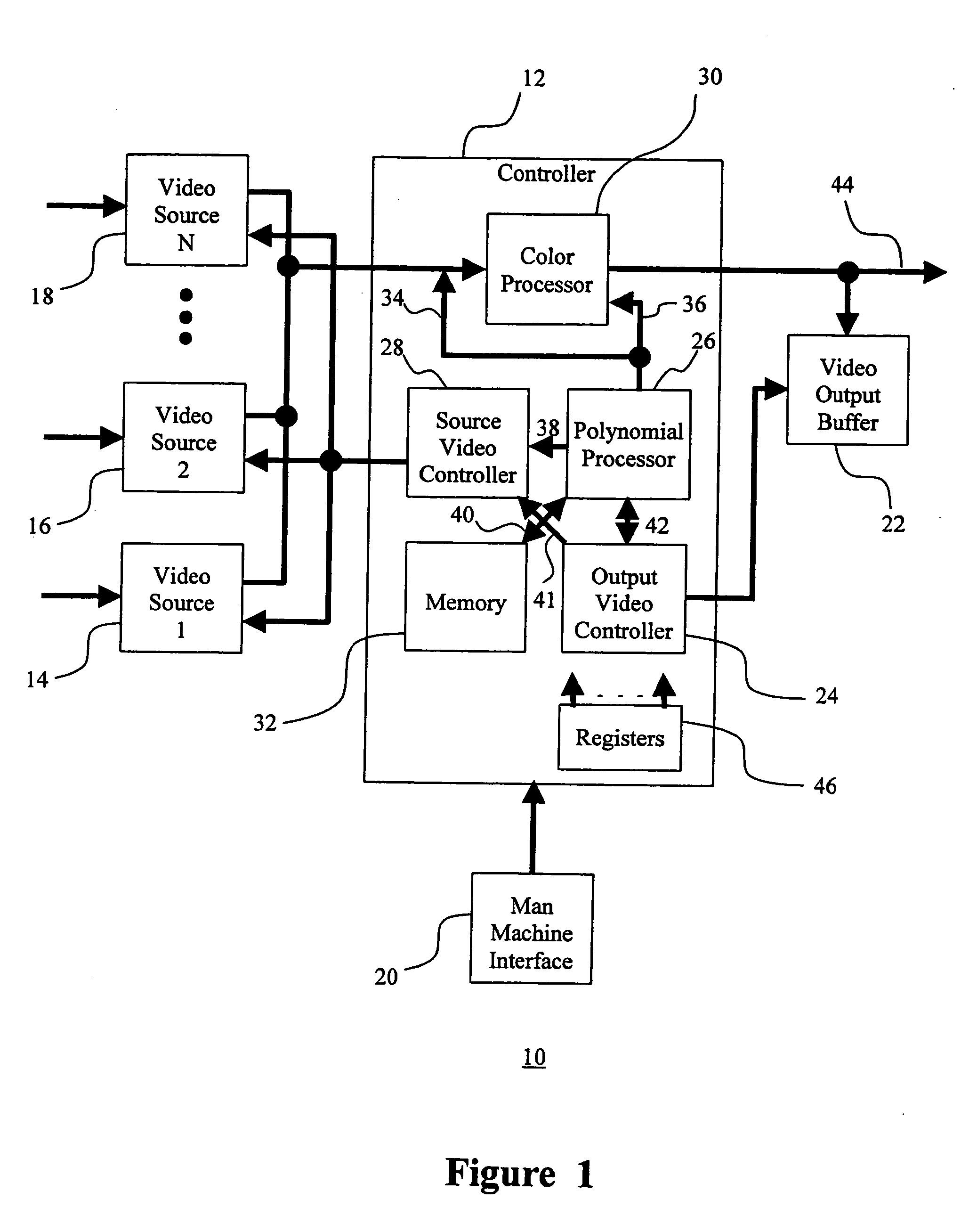
[0045]FIG. 1 is a video rendering system 10 shown generally in accordance with an illustrated embodiment of the invention. Under the illustrated embodiment, the Controller 12 functions to identify and render source pixels into an output video 44 from any of a number of video sources 14, 16, 18. Output video may be displayed on TV monitor, or may be stored in the Video Output Buffer, 22, to be used later.

[0046] Selection of the type of special effect to be rendered may be accomplished through a man-machine interface (MMI) (e.g., a keyboard and monitor) 20.

[0047] In order to render an image, an operator (not shown) may select a video special effect from a list of available effects. Once selected, the video special effect defines several two-variable polynomial functions over the 2-dimensional image space with one variable being the column position, let's call it X, and another variable being the row position of a pixel, call it Y. Each polynomial function has a value for each pixel ...


PUM


Abstract

A method and apparatus are provided for rendering a video image to a destination image space from a plurality of source image spaces. The method includes the steps of generating a set of intermediate incremental values from one or more polynomials, incrementally evaluating the polynomials within a loop processing area of a source or a destination image space along an inner and an outer processing loop based upon the generated set of intermediate incremental values. During the rendering a video image, the method retrieves pixels from a source image space, creates color pattern, or blends the pixels from two source image spaces based upon the evaluated polynomials from the inner and outer loops.

Description

FIELD OF THE INVENTION [0001] The field of the invention relates to video special effects and more particularly to methods of using polynomial functions to create video special effects. BACKGROUND OF THE INVENTION [0002] Video special effects of changing from a source video image to an output video image are generally known. Examples that are generally known include cutting out a portion of video inside a soft-edge heart shape, adding star highlighting into the video, adding words with changing gradient color on the character faces of the word, and rotating, shearing, and resizing the words, the star highlight and the soft-edge heart shape with its video insert. [0003] In cutting out the portion of video inside a soft-edge heart shape, the pixels of the first image located inside the heart shape is identified and copied into the output video image. Those pixels of the first image located near the edge of the heart shape are identified and colors of these pixels are modified based on...

Claims


Application Information

Patent Timeline
IPC IPC(8): G06T15/50H04N5/262H04N9/74
CPCG06T15/503H04N9/74H04N5/262
Inventor CHAO, PHILIP
Owner JET STREAM MEDIA TECH
Why Eureka
Try Eureka