Power connector

a power connector and connector technology, applied in the field of connectors, can solve the problems of not being able to be varied with different requirements, the blade of the panel-form connector b>2/b> must be designed, and the usability is not wide enough, so as to achieve the effect of increasing the flexibility of us

Inactive Publication Date: 2005-12-15
DELTA ELECTRONICS INC
View PDF6 Cites 17 Cited by
  • Summary
  • Abstract
  • Description
  • Claims
  • Application Information

AI Technical Summary

Benefits of technology

[0007] It is an object of the present invention to provide a power connector that can satisfy applications for various panel-form connectors to increase its using flexibility.

Problems solved by technology

However, the electrically conductive blade of the panel-form connector 2 must be designed according to the specified thickness and cannot be varied with different requirements.
The cooperative power connector 1 has an unadjustable opening 112, so it can only satisfy a single connection application and cannot simultaneously satisfy a single-pole and dual-pole connection applications with different thicknesses, thereby lacking a wider usability.
Besides, the conventional power connector 1 also has disadvantages of large volume, complex structure, and difficult assembling.

Method used


Image

  • Power connector
  • Power connector
  • Power connector

Examples


Embodiment Construction

[0034] Some typical embodiments to present the features and advantages of the present invention will be precisely described in the following illustrations. It should be understood that the present invention may have various modifications in different modes, which are not apart from the scope of the present invention, and the illustrations and drawings of the present invention are substantially used for explaining but not for limiting the present invention.

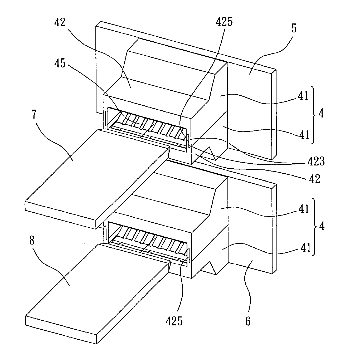
[0035]FIG. 3 is a schematic view showing the power connector according to a preferred embodiment of the present invention. As shown in FIG. 3, the power connector 4 is disposed on the bus bar (not shown) to be used as an electrically conductive interface between the panel-form connector (not shown) and the bus bar. The power connector 4 includes a pair of conductive devices 41 with identical structure, shape and size, and can be assembled with or separated from each other.

[0036]FIG. 4 is a schematic view showing the detailed stru...


PUM


Abstract

A power connector used to be connected with a panel-form connector is disclosed. The power connector comprises a pair of conductive devices, and each conductive device comprises a case, a metal base, and a metal conductive piece combined with the metal base and disposed into the case. The cases of the conductive devices are cooperated with each other to define an opening, and the width of the opening is adjustable by controlling the relative distance between the conductive devices for receiving various panel-form connectors with different thicknesses.

Description

FIELD OF THE INVENTION [0001] The present invention relates to a connector, and more particularly to a power connector. BACKGROUND OF THE INVENTION [0002] Power connectors have been used extensively as connective interfaces in various power delivery systems, such as a power distribution system or a power supply system. The power delivery system usually includes a cabinet, and the cabinet has a bus bar. The power connector is disposed on the bus bar for a hot-plug power supply device to be electrically connected with the power delivery system. [0003]FIG. 1 is a schematic view showing the structure of a conventional power connector. As shown in FIG. 1, the power connector 1 includes a case 11, a conductive clip device 12, and a pair of contact plates13. The case 11 has a top 111 and a bottom 112, wherein the top 111 has an opening 113 extending from the top 111 to the bottom 112, so as to form a receiving space (not shown). The conductive clip device 12 includes a pair of planar sides...

Claims


Application Information

Patent Timeline
Patent Type & Authority Applications(United States)
IPC IPC(8): H01R12/16H01R13/11H01R13/115H01R13/187H01R13/68H01R24/58
CPCH01R13/113H01R12/7088H01R13/187
Inventor YANG, TA-JUNG
Owner DELTA ELECTRONICS INC
Why Eureka
Try Eureka