
Eureka
For R&D, Eureka makes reading and utilizing patents & technical documents easy.
Eureka AIR
Designed for self-driven R&D workflows. Generate viable solutions, solve complex R&D challenges, empower your innovation with AI.

Eureka Materials
Designed for material experts only. Revolutionize your material R&D, from search, analyze, to developing new materials.

TechResearch
Generate reliable direction feasibility study reports for your R&D in just a few steps.

TechSeek
Discover and master advanced knowledge NOW. Basics, ideas, possibilities, all at once.

TechMind
As an expert in R&D Theories, TechMind can generates customized viable solutions instantly.

TechRisk
Analyze your overall solution with one click, know your potential R&D risks in advance.

TechMonitor
Get weekly tech updates, stay abreast of the latest tech innovations and key insights.
Gaming machine
- Summary
- Abstract
- Description
- Claims
- Application Information
AI Technical Summary
Benefits of technology
Problems solved by technology
Method used
Image

Examples
modified example 1
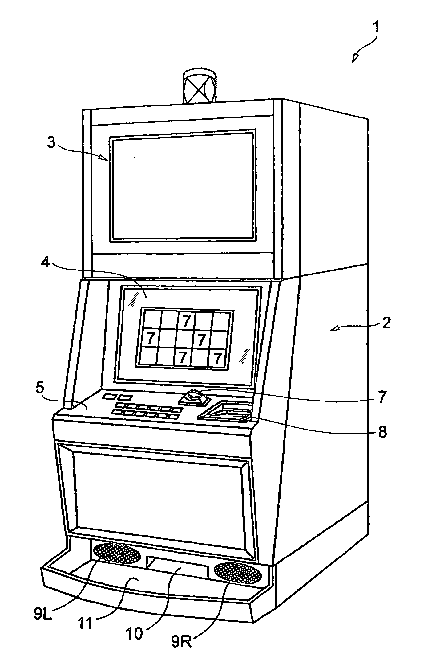
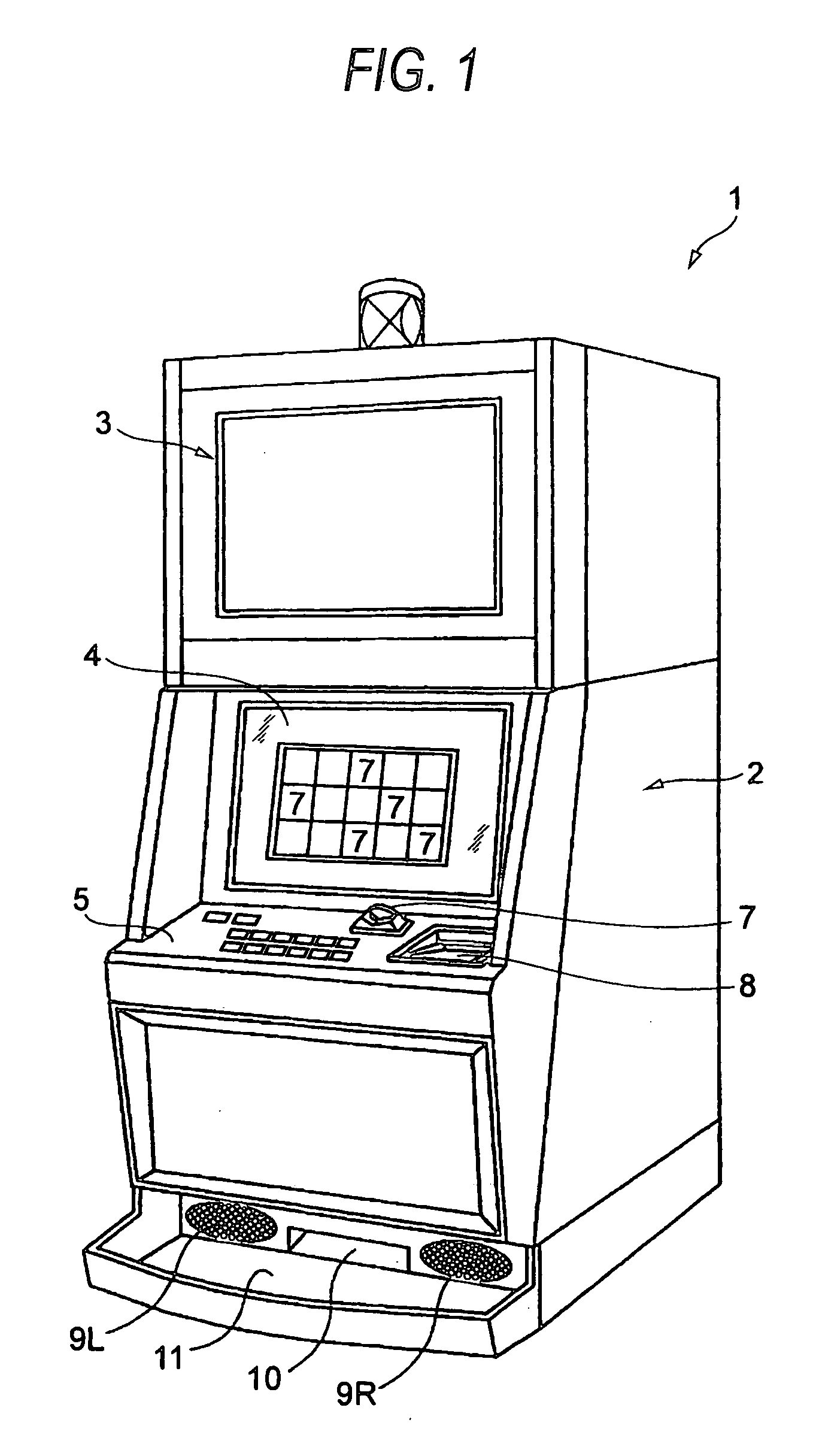
[0116]FIG. 13 is a block diagram mainly showing the internal configuration of a slot machine 52. The slot machine 52 is different from the slot machine 51 in that it has a touch panel 13 as the operation unit, instead of the switch operation button 12. This touch panel 13 is disposed covering a surface of not-shown protective glass on the front side of a lower image display panel 4. This touch panel 13 detects a position (contact position) touched by a finger of the player or any other contact body, and inputs to a CPU 32 an identification code serving as corresponding input information which corresponds to the contact position.
[0117] Besides, in the slot machine 52, a ROM 34 stores a display pattern table 115 shown in FIG. 18 and has the function of serving as the display mode storage unit of the invention. The display pattern table 115, having an identification code area 115a and a display pattern area 115b, stores display pattern codes for specifying a plurality of display patte...
modified example 2
[0122] A modified example of the slot machine 51 will now be described. This slot machine 51 is configured such that, as shown in FIGS. 19A, 19B, and 19C, in a lower image display panel 4, a common image region 4a and a position adjustment region 4b are secured by means of an image control CPU 71a serving as the display control unit. In the case of FIG. 19A, the common image region 4a, disposed in the center of the lower image display panel 4, is a region capable of displaying a common image. The position adjustment region 4b (shaded in FIGS. 19A to 19C), having first to fourth position adjustment regions 4b1, 4b2, 4b3, and 4b4 that are disposed adjacent to the periphery of the common image region 4a, is a region (at four corners of which spare regions 4b9 are secured) for use in adjusting the display position of the common image. In the case of FIG. 19B, two position adjustment regions 4b5 and 4b6 are disposed on both the left and right sides of the lower image display panel 4, and...
PUM
 Abstract
Description
Claims
Application Information
 - R&D Engineer
- R&D Manager
- IP Professional
- Industry Leading Data Capabilities
- Powerful AI technology
- Patent DNA Extraction
Browse by: Latest US Patents, China's latest patents, Technical Efficacy Thesaurus, Application Domain, Technology Topic, Popular Technical Reports.
© 2024 PatSnap. All rights reserved.Legal|Privacy policy|Modern Slavery Act Transparency Statement|Sitemap|About US| Contact US: help@patsnap.com