Eureka AIR delivers breakthrough ideas for toughest innovation challenges, trusted by R&D personnel around the world.

Image information apparatus and module unit

Inactive Publication Date: 2007-07-19
MITSUBISHI ELECTRIC CORP
View PDF18 Cites 49 Cited by
  • Summary
  • Abstract
  • Description
  • Claims
  • Application Information

AI Technical Summary

Benefits of technology

[0017] An objective of the present invention, which is made to solve problems as described above, is to configure an apparatus without accompanying entirely changing and revising the system LSI even if the specification of the apparatus or the system LSI configuring the apparatus is changed, and also to obtain an apparatus in which development cost can be reduced and development period can be shortened.
[0020] Because the present invention is configured as described above, it is effective that, even if the specification of an apparatus or a system LSI configuring the apparatus is changed, not only the apparatus can be configured without entirely changing and revising the system LSI, but also development cost can be reduced and the development period can be shortened.

Problems solved by technology

Therefore, software installed in this system LSI must be entirely changed and revised; consequently, a problem has been that development cost and development period increase.
In an apparatus in which a system LSI whose function has already been obsolete is installed, a problem has also been that new functions cannot be realized without revising and updating the system LSI itself.
Moreover, because in most cases, the exclusive function of the system LSI differs model by model of the apparatus provided with the system LSI, in order to realize such exclusive function, a system LSI exclusive to the apparatus must be developed; consequently, another problem has also been that cost reduction is difficult.
Furthermore, because the product specification is changed every time the system LSI is changed, reliability test and EMI test must be newly conducted every time it is changed; consequently, a problem has been that time and cost for the tests increase.

Method used


Image

  • Image information apparatus and module unit
  • Image information apparatus and module unit
  • Image information apparatus and module unit

Examples


embodiment 1

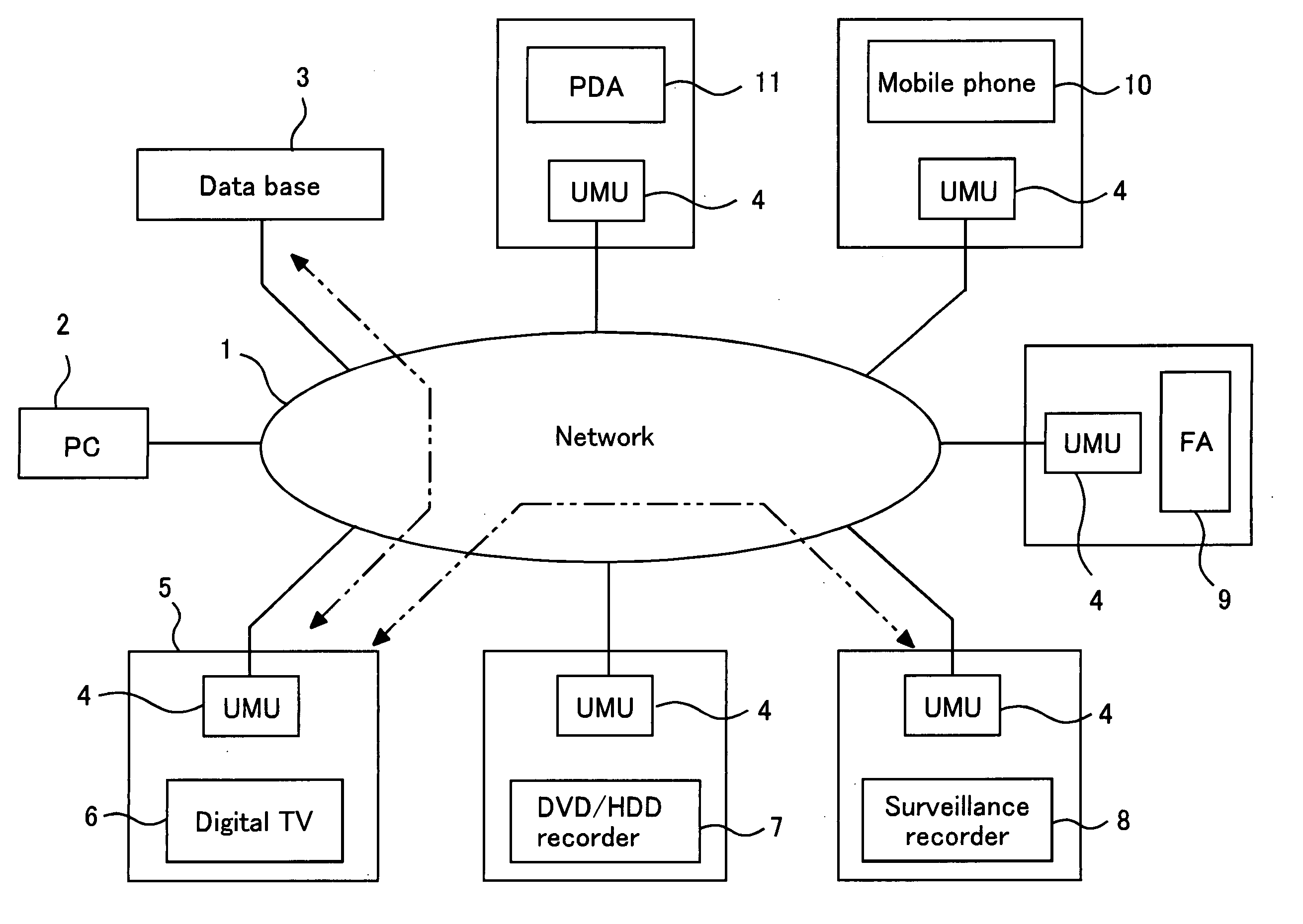
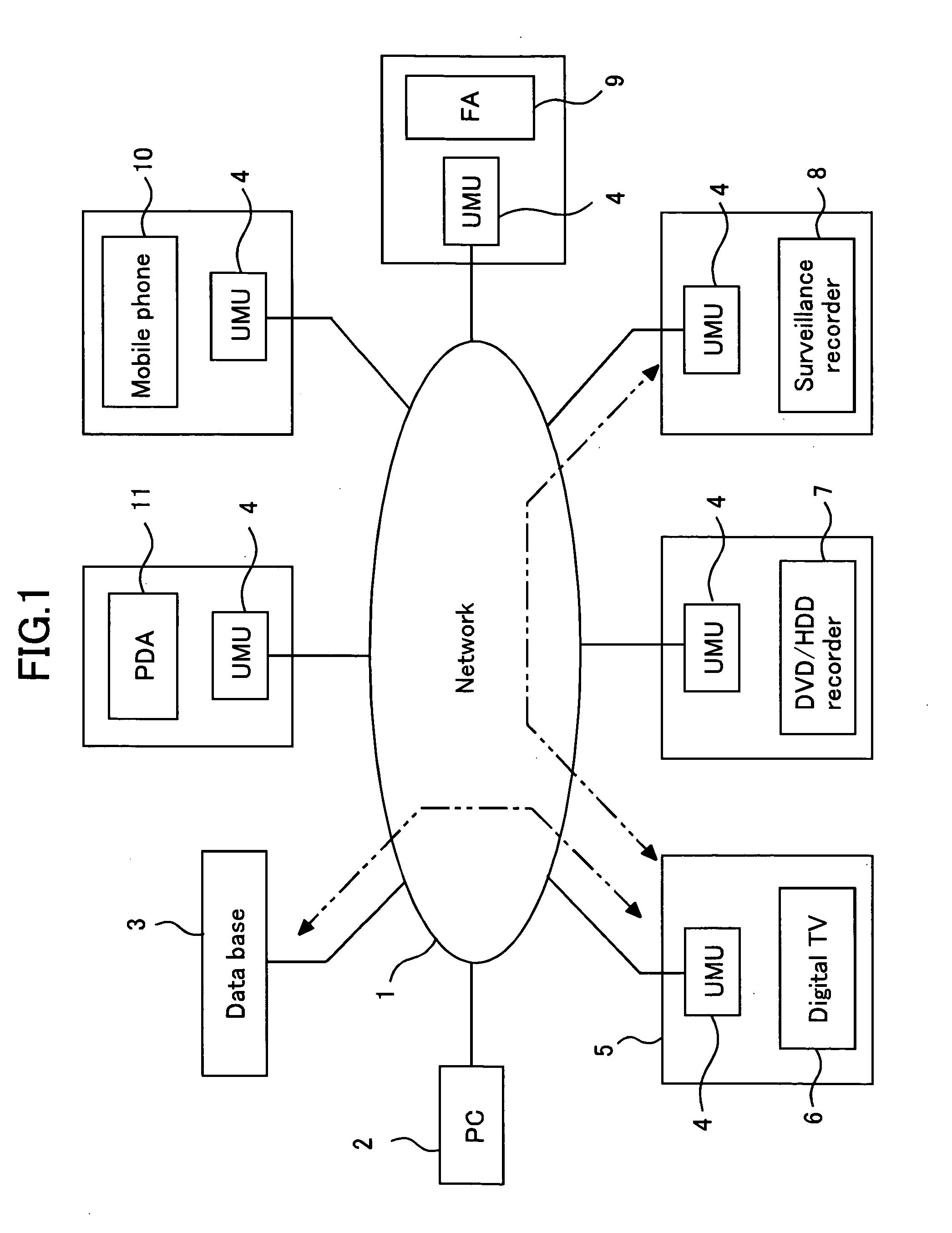
[0080]FIG. 1 is a view illustrating a network system including image information apparatuses according to Embodiment 1 of the present invention. Here, various kinds of image information apparatuses such as a digital television (digital TV), a DVD / HDD recorder, a monitor recorder, an FA (factory automation) apparatus in a factory, a mobile phone, and a PDA (personal digital assistant) that are illustrated as examples in FIG. 1, are connected to a network through their respective module units.

[0081] A network 1 is a network represented by a small-scale LAN and the large-scale Internet. Generally, client computers that are not illustrated are connected to the network, and a server for offering service to each client computer and for sending and receiving data is also connected to the client computers.

[0082] A computer (here, a personal computer is used as an example, and hereinafter referred to as a “PC”) PC 2 is a personal computer connected to the network 1 and is used for various ...

embodiment 2

[0228]FIG. 28 is a view illustrating an example of a system configuration, when the ubiquitous image module 12 is connected to an Ethernet interface of the image information apparatus 40.

[0229] The ubiquitous image module unit 4 including the ubiquitous image module 12 has an Ethernet interface 32f, which is connected to an Ethernet interface 31e of the image information apparatus 40.

[0230] Due to the connection with this ubiquitous image module unit 4, the image information apparatus 40 can communicate with and control, through a network such as an LAN, other apparatuses, such as network cameras 34d, 34e, and 34f that are connected to the LAN 33.

[0231] Here, in the image information apparatus 40, although a protocol used for communicating with and controlling a NAS is installed, a protocol for communicating with and controlling the network cameras provided outside the apparatus is not installed. In such a case, by connecting the ubiquitous module unit 12, the image information a...

embodiment 3

[0262]FIG. 38 is a view illustrating an example of a system configuration, when the ubiquitous image module unit 4 is connected to the image information apparatus 40. The image information apparatus 40 illustrated in FIG. 38 is configured to include the S-I / F 31, instead of the driver 55 and the host interface 56 illustrated in FIG. 7.

[0263] Moreover, the ubiquitous image module unit 4 is configured to include the ubiquitous image module 12 and the U-I / F 32. By connecting each of the interfaces S-I / F 31 and the U-I / F 32, without development of a new system LSI, the image information apparatus 40 having the function of the ubiquitous image module 12 can be realized.

[0264] After connecting to the Internet environment through the communication engine 24, the ubiquitous image module unit 4 downloads image and audio data, etc. from the other image information apparatus connected to the Internet.

[0265] The image and audio data, etc. downloaded undergoes decode processing or graphic pro...


PUM


Abstract

An apparatus has not been configured without accompanying entirely changing and revising the system LSI when the specification of the apparatus or the system LSI configuring the apparatus is changed, and also, development cost has not been able to be reduced and development period has not been able to be shortened. An image information apparatus is realized in which new functions are easy to be added into the image information apparatus without need for development of a new system LSI for each model, by installing into the image information apparatus a ubiquitous image module having configurational elements such as a hardware engine, CPU, and general-purpose bus for realizing functions that have not been provided on the image information apparatus itself, and also including an OS for operating the configurational elements.

Description

BACKGROUND OF THE INVENTION [0001] 1. Field of the Invention [0002] The present invention relates to image information apparatuses, and particularly relates to an image information apparatus and a module unit used in the apparatus, which can ubiquitously connect to network environments, by providing the apparatus with a ubiquitous image module or a ubiquitous-image-module unit configured including the ubiquitous image module. [0003] 2. Description of the Related Art [0004] A conventional AV (audio visual) digital network apparatus includes in its interior an interface for connecting to a network and a function for connecting to the network (for example, refer to Patent Document 1). [0005] Moreover, a function relating to a network is also realized using a system LSI (large scale integration) (for example, refer to Patent Document 2). [0006] [Patent document 1] Japanese Laid-Open Patent Publication 016,619 / 2002 (on pages 5-6, in FIG. 1) [0007] [Patent document 2] Japanese Laid-Open P...

Claims


Application Information

Patent Timeline
IPC IPC(8): G05B15/00G06F9/44G06F9/46G06F3/14G06F13/00H04N21/226H04N21/241H04N21/443H04N21/81
CPCG06F3/14
Inventor MISAWA, TENRYUYOSHIMOTO, KYOSUKEMURAKAMI, TOKUMICHIMIZUTANI, YOSHIKIHIRASAWA, KAZUOMORITA, CHIHIROYAGI, KOSUKE
Owner MITSUBISHI ELECTRIC CORP
Why Eureka
Eureka Blog
Learn More