
Co-design of a testbench and driver of a device

Active Publication Date: 2013-01-03
NAT ICT AUSTRALIA
View PDF20 Cites 14 Cited by
  • Summary
  • Abstract
  • Description
  • Claims
  • Application Information

AI Technical Summary

Benefits of technology

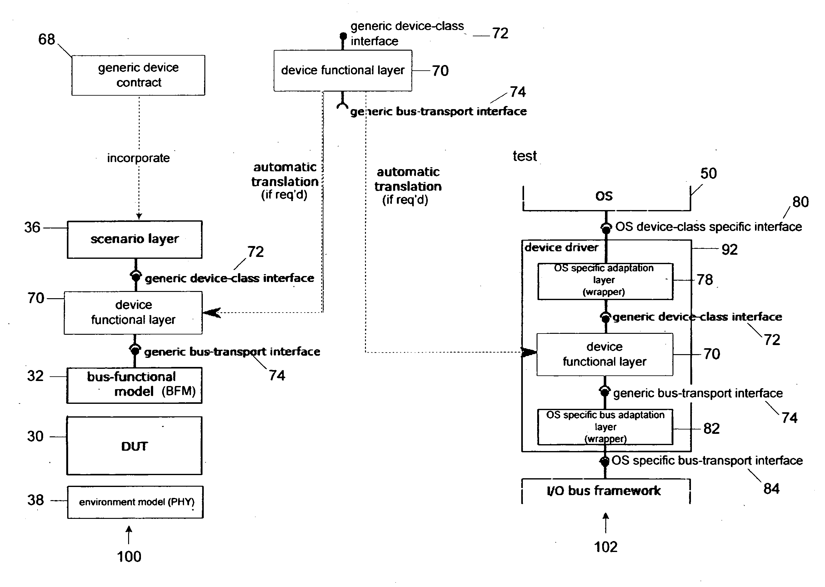
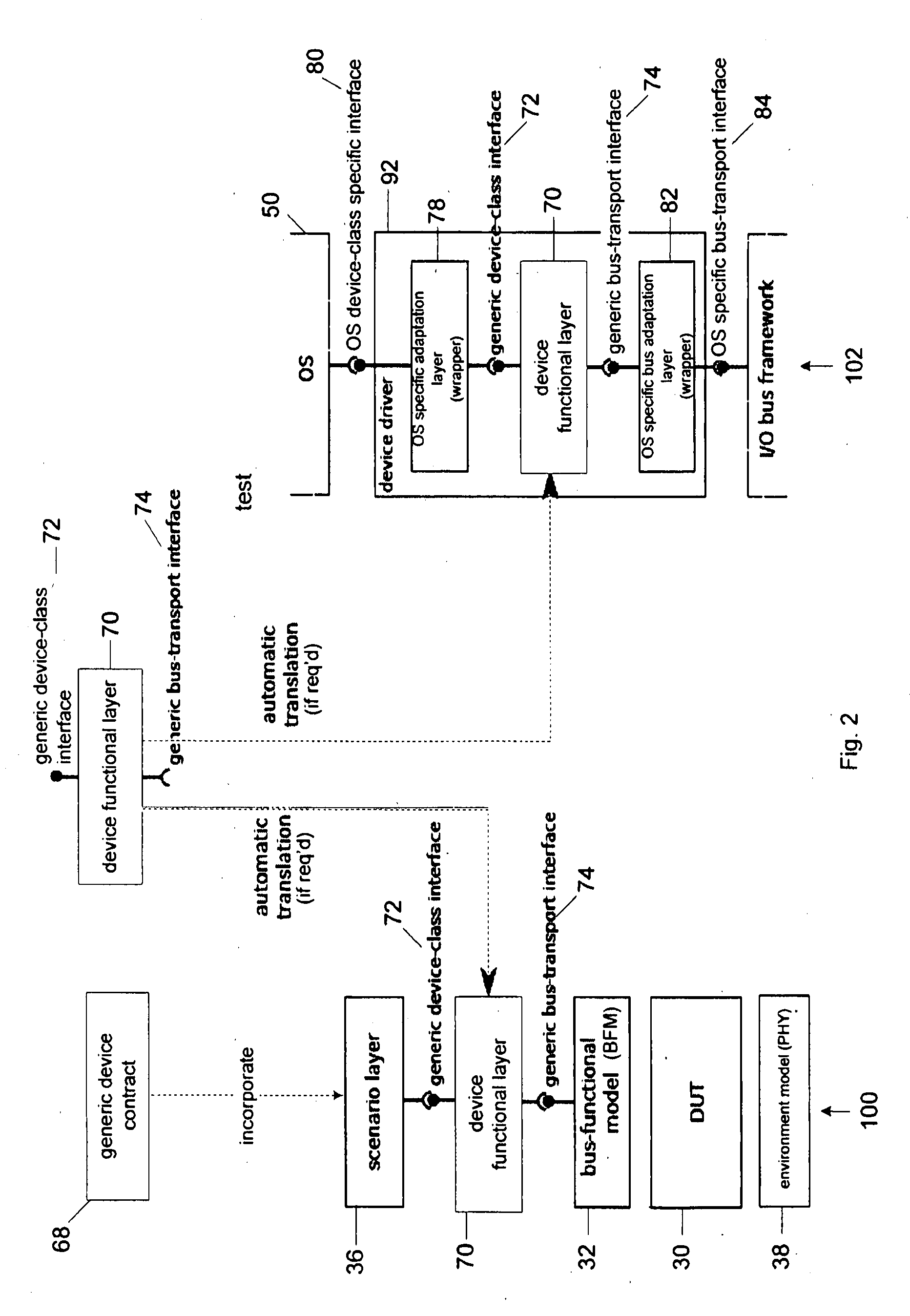
This patented technology improves driver reliability and reduces development costs by re-using the device interface implementation as the core part of the device driver. The generic device interface, which is dependent on the device class, increases efficiency by being constructed once for each device class. This means that the same part of the code is used for all devices in the same class, which simplifies the driver's development.

Problems solved by technology

Drivers are the leading reliability hazard in modern OSs.
The leading class of driver defects, comprising about 40% of all driver bugs, are related to incorrect handling of the hardware-software interface.
These device hardware-software interface bugs include incorrect use of device registers, sending commands to the device in the wrong order, or incorrectly interpreting device responses.
Since mistakes are expensive and time consuming to fix once the design has been synthesised in silicon, much effort is put into initially testing / verifying the design in a simulated environment called a ‘testbench’ prior to producing hardware.
In practice, datasheets are often incomplete and inaccurate, which results in numerous driver defects.
Another problem that driver developers face is the complexity of testing the driver.
This makes thorough testing difficult to achieve.
For instance, testing how the driver handles internal device FIFO overflow due to bus contention or packet transmission failure due to multiple network collisions is difficult in practice.
As a result, most drivers are only well tested in common scenarios and do not adequately handle various corner cases.

Method used


Image

  • Co-design of a testbench and driver of a device
  • Co-design of a testbench and driver of a device
  • Co-design of a testbench and driver of a device

Examples


example 2

[0129]FIG. 5 shows the device-driver design workflow. This workflow is integrated into the hardware design and verification workflow. The workflow consists of the following tasks and the steps as performed by a computer system will be described:

Generic Interface Specification 200

[0130]This involves specifying the generic device-class interface 72, the generic bus transport interfaces 74, and the device-class contract 68. This task is carried out once for each device class and each bus type. The processor of a computer system receives at an input port electronic files representative of the interfaces 72 and 74. Alternatively, the computer system may operate to access the interfaces 72 and 74 stored in local or remote memory.

OS Framework Implementation 206

[0131]This involves implementing OS adaptation layer 78 and bus adaptation layer 82 for a particular OS and a particular device class or bus type. This task is carried out once for each OS and each device class or bus type. Again, th...

example 3

[0138]A variation of the flow shown in FIG. 5 is shown in FIG. 6, where the same steps are marked with the same reference numbers. However, in FIG. 6 the step of developing 250 the functional layer 70 is defined as a separate task that is performed before the testbench design 202, 204 task. This allows synthesising 208, 210 a driver 92 for the device before or concurrently with RTL design 224 and verification 226. This approach facilitates early system prototyping. Defects in the functional layer 70 are detected in the process of RTL verification 226, and task feedback 94 can be delivered to the functional layer implementation task 250 so as to create an improved functional layer 70 that can be used in further test bench design 202, 204 and driver synthesis 208, 210.

example 4

[0139]Yet another variation of the flow shown in FIG. 5 is shown in FIG. 7, where the same steps are marked with the same reference numbers. However, FIG. 7 relates to devices that do not fall precisely into one of existing device classes. For example, many devices implement unique features that are not found in other similar devices. Supporting such features requires developing extensions 240 to produce extended generic device-class 72′ and extended bus transport 73′ interfaces. Also extensions 242 to produce an extended OS adaptation layer 78′ and an extended bus adaptation layer 92′. To this end, the design workflow is modified to repeat tasks 200 and 206 on per-device basis. The modified workflow is shown in FIG. 7.

[0140]It will be appreciated by persons skilled in the art that numerous variations and / or modifications may be made to the invention as shown in the specific embodiments without departing from the scope of the invention as broadly described.

[0141]It should be underst...


PUM


Abstract

This disclosure concerns the co-design of a testbench (100) and driver (102) of a device. It is an advantage in at least some embodiments that it improves driver reliability and reduces development cost. It does this by re-using the device functional layer (70) that is dependent on the device class but independent of the specific device and specific operating system (OS) of the driver. The device functional layer (70) is re-used as it is implemented in the device's testbench (100) and also as the core part of the device (driver (102). A scenario layer (68) is also used that is able to test the generic device interface (72) and device functional layer (70) in the testbench (100) environment, and the testing includes testing for responses to OS requests. This helps provide more exhaustive testing.

Description

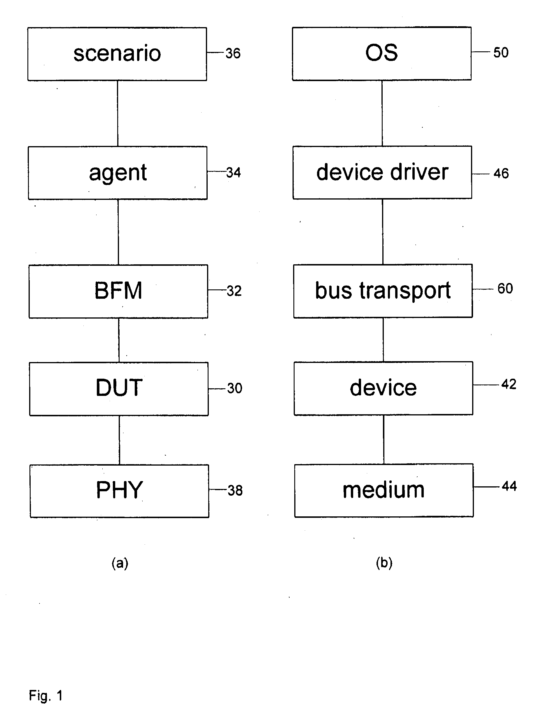
CROSS-REFERENCE TO RELATED APPLICATIONS[0001]The present application claims priority from Australian provisional patent applications No. 2010903329 and No. 2010900663 the content of which is incorporated herein by reference.TECHNICAL FIELD[0002]This disclosure concerns the co-design of a testbench and driver of a device. A testbench is technical field of a hardware verification engineer, whereas a device driver is the technical field of a software developer. Aspects of the invention include a device driver, a computer system, a test bench, a method of constructing a device driver, and also software and a computer system.BACKGROUND ART[0003]Device drivers are critical components of an operating system (OS), as they are the software that controls peripheral hardware, such as disks, network interfaces or graphics displays. They make up a large fraction of OS code, for example around 70% in Linux.[0004]Drivers are the leading reliability hazard in modern OSs. Drivers are known to be res...

Claims


Application Information

Patent Timeline
IPC IPC(8): G06F13/10
CPCG06F11/3664G06F17/5022G06F30/33
Inventor RYZHYK, LEONIDHEISER, GERNOT
Owner NAT ICT AUSTRALIA
Learn More