Variable intake system of a vehicle

a variable intake system and vehicle technology, applied in the direction of charging feed system, combustion engine, combustion air/fuel air treatment, etc., can solve the problems of loss of flow pressure or velocity within parts of the system, system size is too large, etc., to enhance system layout, enhance flow pressure, and enhance flow velocity

Inactive Publication Date: 2005-12-22
HYUNDAI MOTOR CO LTD +1
View PDF4 Cites 13 Cited by
  • Summary
  • Abstract
  • Description
  • Claims
  • Application Information

AI Technical Summary

Benefits of technology

[0005] The present invention provides a variable intake system of a vehicle having non-limiting advantages of an enhanced flow pressure, an enhanced flow velocity, and an enhanced system layout.

Problems solved by technology

However, existing variable intake systems have a number of drawbacks, including the loss of flow pressure or velocity within parts of the system.
Such systems are also too large.

Method used


Image

  • Variable intake system of a vehicle
  • Variable intake system of a vehicle
  • Variable intake system of a vehicle

Examples


Embodiment Construction

[0018] An embodiment of the present invention will hereinafter be described in detail with reference to the accompanying drawings.

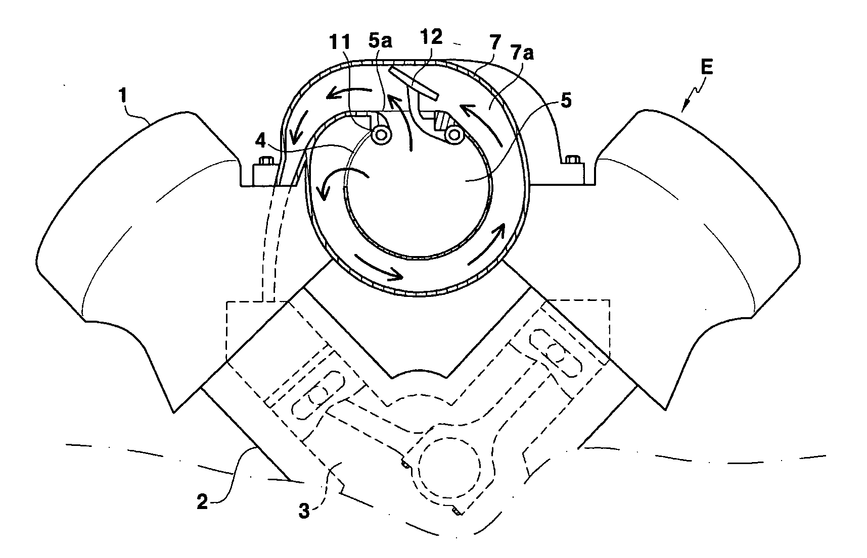
[0019] Generally, as shown in FIG. 1, the function of an intake system of a vehicle is to inject air into a cylinder 3. An intake system includes a plenum 5, and an intake manifold 7. The plenum 5 injects external air into the intake system. The intake manifold 7 has a runner 7a for guiding the air of the plenum 5 into the cylinder 3. A connecting passage 4 for connecting the plenum 5 and the intake manifold 7 is formed at an end of the intake manifold 7. As mentioned above, it is advantageous if a length of the runner 7a of the intake manifold 7 is varied according to a vehicle driving condition. That is, when an engine rpm is high, it is preferable that a length of the runner 7a of the intake manifold 7 becomes short. When an engine rpm is low, it is preferable that a length of the runner 7a of the intake manifold 7 becomes long.

[0020] Typical variabl...


PUM


Abstract

A variable intake system of a vehicle includes a plenum into which an external air is flowed, an intake manifold comprising a plurality of runners connected with the plenum and respectively guiding the air of the plenum into a plurality of cylinders, and a varying unit controlling a length of the runners according to a vehicle driving condition.

Description

CROSS REFERENCE TO RELATED APPLICATIONS [0001] This application is based on, and claims priority to, Korean Application No. 10-2004-0046110, filed on Jun. 21, 2004, the disclosure of which is hereby incorporated by reference. FIELD [0002] The present invention relates to an intake system of a vehicle. More particularly, the present invention relates to a variable intake system of a vehicle. BACKGROUND [0003] Generally, an intake system of a vehicle is to flow air into a cylinder, and includes a plenum, and an intake manifold. The plenum is where external air flows in from outside. The intake manifold has a runner for guiding the air of the plenum into the cylinder. When an engine's rpm is high, it is preferable that a length of the runner of the intake manifold is short, and when the engine's rpm is low, it is preferable that a length of the runner of the intake manifold becomes long. A system that controls the length of the runner based on engine rpm is usually called a variable in...

Claims


Application Information

Patent Timeline
Patent Type & Authority Applications(United States)
IPC IPC(8): F02B27/02F02D9/10F02M35/10F02M35/116
CPCF02B27/02F02B27/0263F02D9/1095Y02T10/146F02M35/10065F02M35/10072F02M35/116F02M35/10039F02B27/0215F02B27/0273Y02T10/12
Inventor PARK, DAE SUNG
Owner HYUNDAI MOTOR CO LTD
Why Eureka
Try Eureka