Anti-vibration tube support

a tube support and anti-vibration technology, applied in the direction of indirect heat exchangers, safety devices for heat exchange apparatuses, lighting and heating apparatuses, etc., can solve the problems that many of the known types of tube supports do not lend themselves to this simple, and achieve the effect of reducing the possibility of tube damag

Inactive Publication Date: 2005-12-22
EXXON RES & ENG CO
View PDF28 Cites 29 Cited by
  • Summary
  • Abstract
  • Description
  • Claims
  • Application Information

AI Technical Summary

Benefits of technology

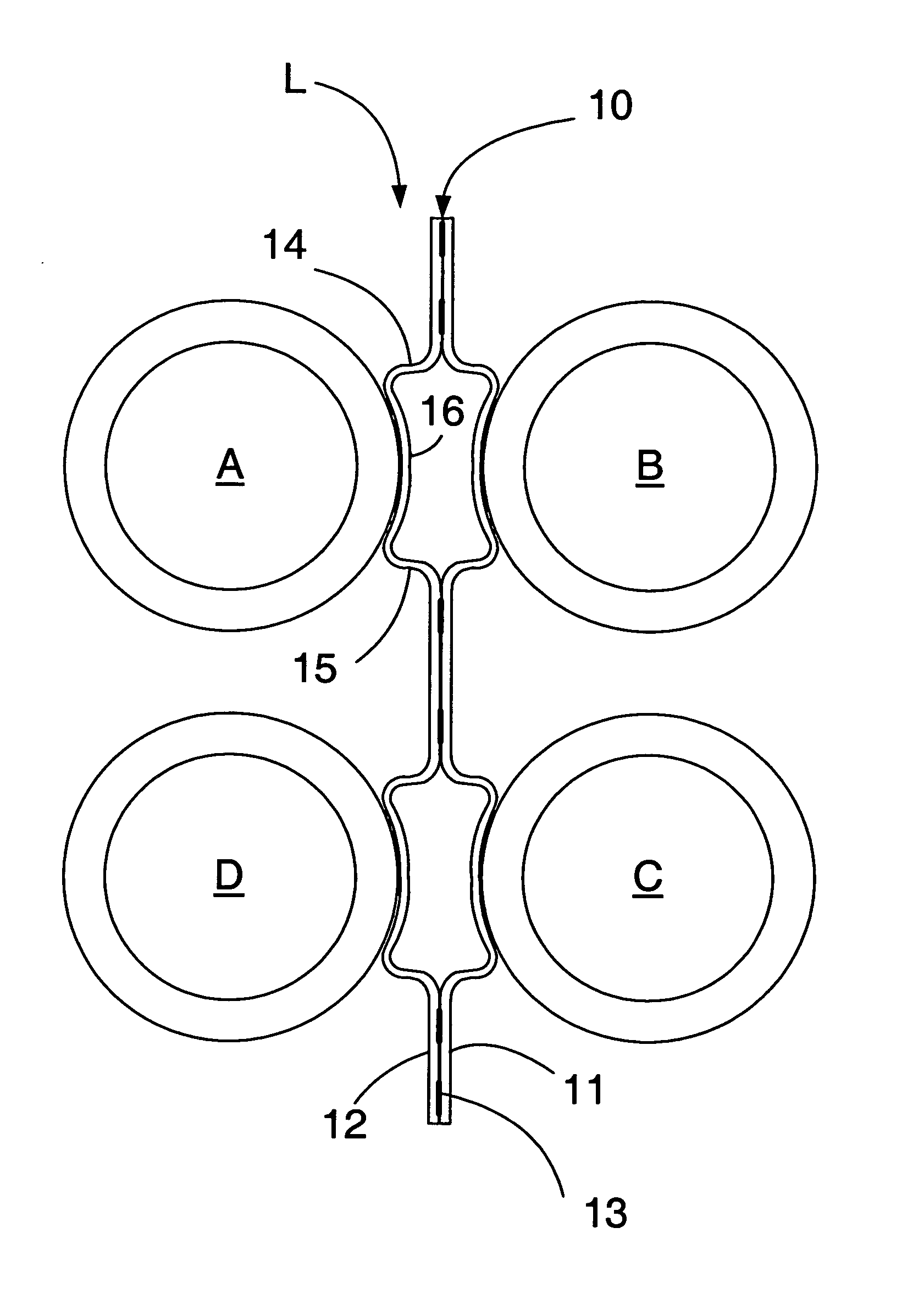
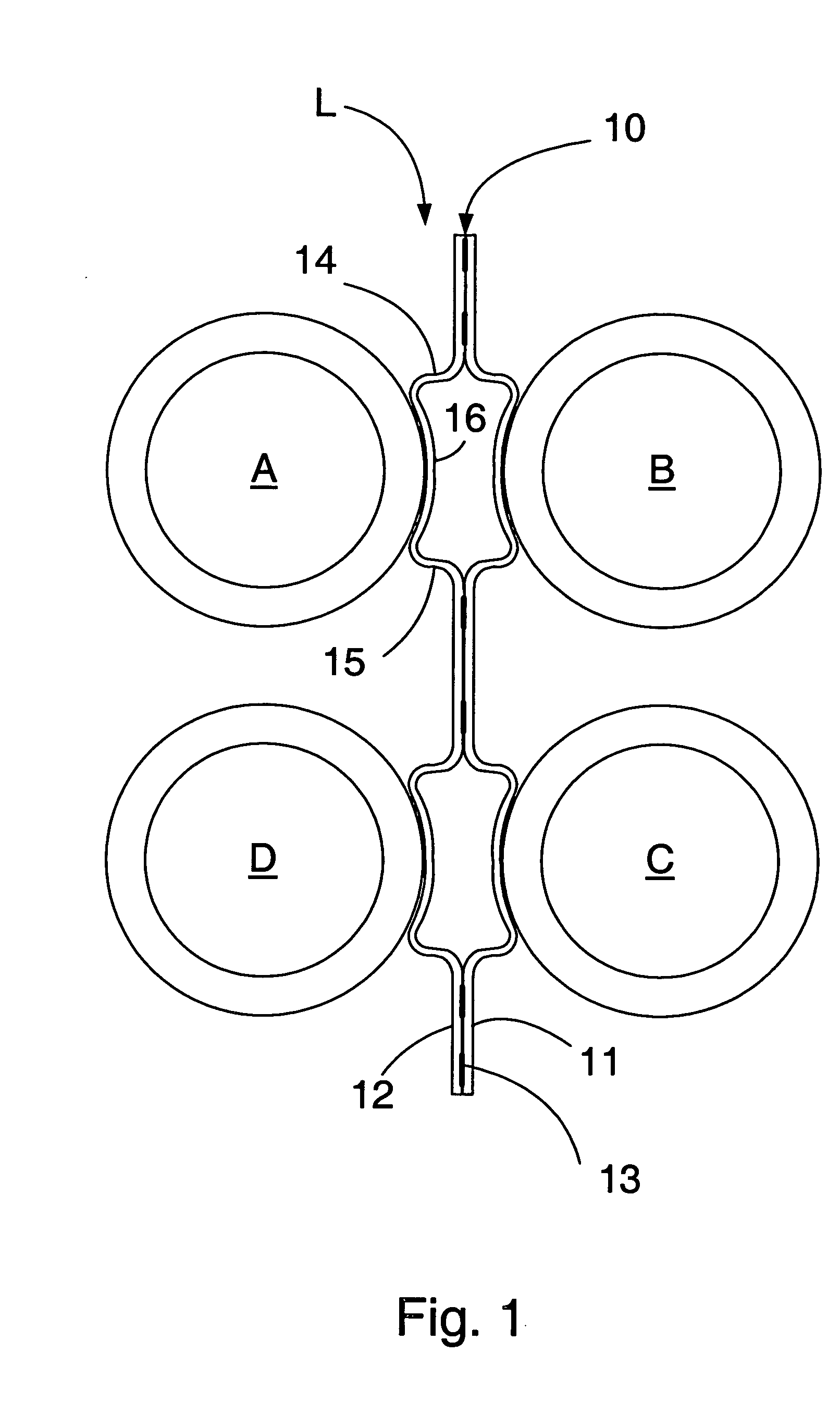
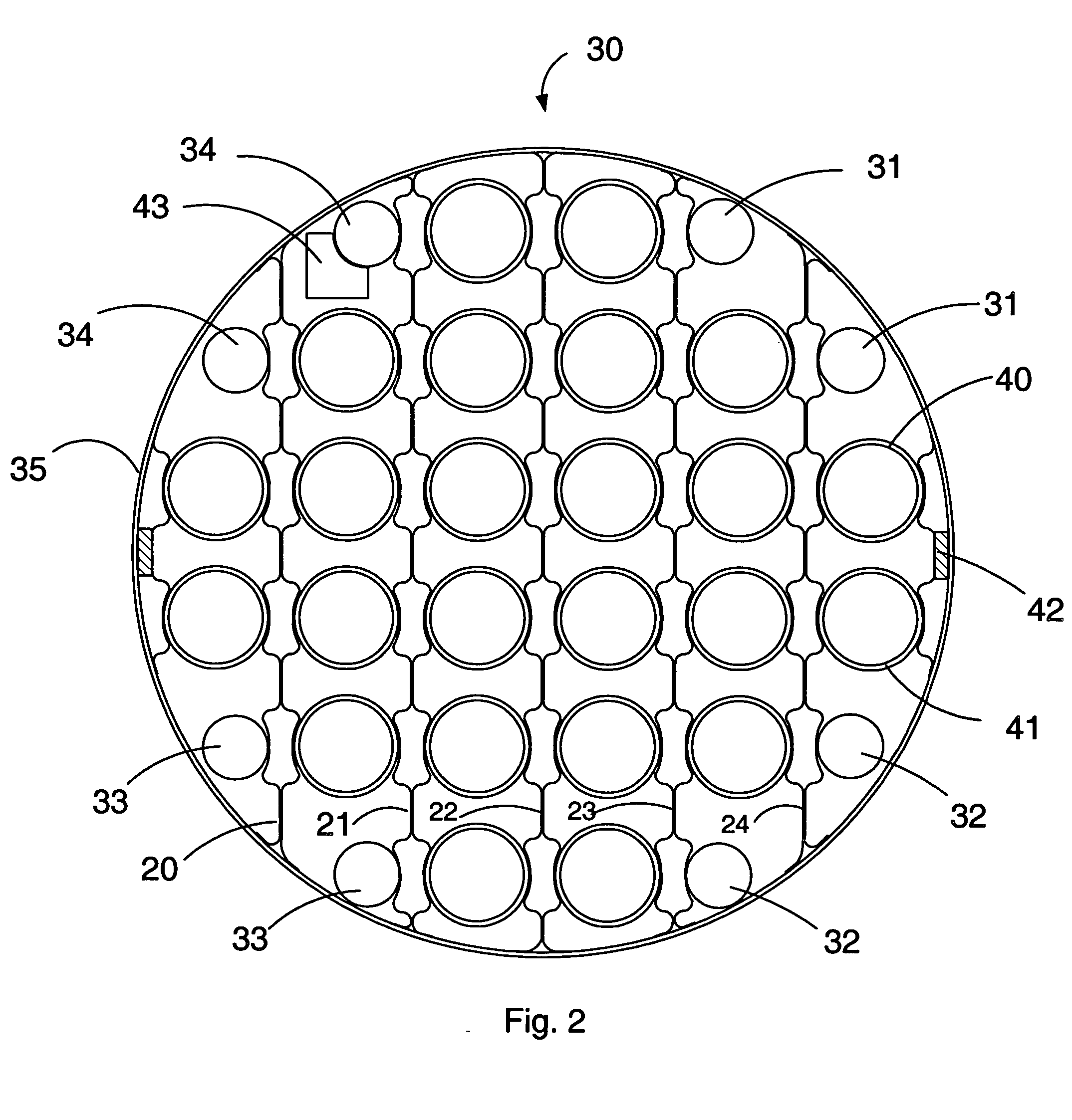
[0011] According to the present invention, a tube support or tube stake is used with in-line tube arrangements (rectangular tube configurations) to mitigate the possibility of tube damage from flow-induced vibration in the tube bundle of the heat exchanger, condenser or other collection of tubes, for example, in devices such as nuclear reactors, electrical heaters, or any collection of parallel cylindrical shapes that has a fluid flow passing over them. The tube support comprises a flat, elongated member or strip which is intended to be inserted in a tube lane between the tubes of the tube bundle. Raised-tube-engaging zones which include transverse, arcuate tube-receiving saddles are disposed along the length of the strip at successive longitudinal locations corresponding to the tube positions in the bundle. These tube-engaging zones extend laterally out from each face of the member opposite one another at each location; they extend away from the medial plane of the member, so that the saddles receive and closely hold the tubes on opposite sides of the tube lane.

Problems solved by technology

Many of the known types of tube support do not lend themselves to this simple, economical and convenient method of fabrication.

Method used


Image

  • Anti-vibration tube support
  • Anti-vibration tube support
  • Anti-vibration tube support

Examples


Embodiment Construction

[0019] The tube support or tube stake of the present invention is arranged to provide direct support for tubes which are adjacent to one another but on opposite sides of a tube lane. The tube support may be inserted between the tubes in the tube bundle along a tube lane between adjacent tube rows. Where the construction of the exchanger permits, the support may be made sufficiently long to extend from one side of the tube bundle to the other to provide support for the tubes across the entire width of the bundle; in this case, the length of the tube supports will vary according to the length of the tube lanes across the bundle. In many cases, however, the location of pass lanes in the bundle will create discontinuities in the lanes so that it will not be possible to insert the supports all the way across the bundle. In such cases, it may be possible to insert the supports into the bundle from different sides of the bundle at different locations along the length of the bundle so as to...


PUM


Abstract

A tube support device is used with tube bundle devices such as heat exchangers or, condensers with in-line tube arrangements (rectangular tube configuration) to mitigate the possibility of tube damage from flow-induced vibration in the tube bundle. The tube support comprises an elongated member or strip which is intended to be inserted in a tube lane between the tubes of the tube bundle. Raised-tube-engaging zones which include transverse, arcuate tube-receiving saddles are disposed along the length of the strip at successive longitudinal locations corresponding to the tube positions in the bundle. These tube-engaging zones extend laterally out, away from the medial plane of the strip, so that the saddles receive and closely hold the tubes on opposite sides of the tube lane. The support device may be made of two strips joined back-to-back with the tube-engaging zones extending out from one face of each strip or, alternatively, by a single strip with longitudinal slits which enable the tube-engaging zones to extend out on alternate faces of the strip at each tube location.

Description

[0001] This application claims the benefit of U.S. Ser. No. 60 / 580,984 filed Jun. 18, 2004.CROSS REFERENCE TO RELATED APPLICATIONS [0002] Application Ser. No. 10 / 848,903 filed 19 May 2003, Publication No. 20050006075A1, entitled “Anti-Vibration Tube Support” of A. S. Wanni, M. M. Calanog, T. M. Rudy, and R. C. Tomotaki relates to a different type of anti-vibration tube support. FIELD OF THE INVENTION [0003] This invention relates to tube support devices, commonly referred to as tube stakes which are useful with tube bundles in heat exchangers and similar fluid-handling equipment. BACKGROUND OF THE INVENTION [0004] Tube bundle equipment such as shell and tube heat exchangers and similar items of fluid handling devices utilize tubes organized in bundles to conduct the fluids through the equipment. In such tube bundles, there is typically fluid flow both through the insides of the tubes and across the outsides of the tubes. The configuration of the tubes in the bundle is set by the tub...

Claims


Application Information

Patent Timeline
Patent Type & Authority Applications(United States)
IPC IPC(8): F28F9/013
CPCF28F2265/30F28F9/0132
Inventor WANNI, AMAR S.CALANOG, MARCIANO MADRIDRUDY, THOMAS M.KEEN, MALCOLM D.
Owner EXXON RES & ENG CO
Why Eureka
Try Eureka