Elevator system

Inactive Publication Date: 2005-12-22
TK ELEVATOR INNOVATION & OPERATIONS GMBH
View PDF23 Cites 60 Cited by
  • Summary
  • Abstract
  • Description
  • Claims
  • Application Information

AI Technical Summary

Benefits of technology

[0010] A further gain in safety is achieved in the case of the elevator system according to the invention by the control units of at least all the cars of one traveling path being connected to one another and altogether forming a group control device. The movements of all the cars moving along a common traveling path can be monitored by means of the group control device. The group control device comprises the control units respectively associated with a car, which are connected in a wire-bound or wireless manner to one another and, by their interaction, control all the cars. This makes it possible to dispense with a higher-level central unit for the cars of one traveling path. The control units are preferably connected to one another via a BUS system. Alternatively, separate connecting lines may be used. A connection via light guides may also be provided, or the connection may be wireless, for example by radio or light. The elimination of a higher-level central unit allows the elevator system to be made particularly immune to faults, since the failure of an individual control unit merely has the consequence that the car associated with this control unit can no longer be used, but the operation of the remaining cars remains uninfluenced by this.
[0048] In this respect it is advantageous if the safety device comprises a determining unit for determining a speed-dependent and advantageously also traveling-direction-dependent minimum distance. A configuration of this type has the advantage that, when two cars slowly approach each other, a smaller minimum distance can be used for triggering a safety gear than when the cars approach each other quickly. In particular, it may be provided that, on the occasion of inspection or servicing travel, with very low speed of the cars, the minimum distance can be preselected by the determining unit to the value 0, so that two cars can come right up against each other without a safety gear being triggered. The minimum distance required for triggering a safety gear can consequently be electronically monitored by means of the determining unit.

Problems solved by technology

If the safety device establishes by comparison of the actually existing distance with the critical distance that the actual distance is below the critical distance, and consequently the risk of a car collision exists, the safety device triggers an emergency stop of the car.

Method used


Image

  • Elevator system
  • Elevator system
  • Elevator system

Examples


first embodiment

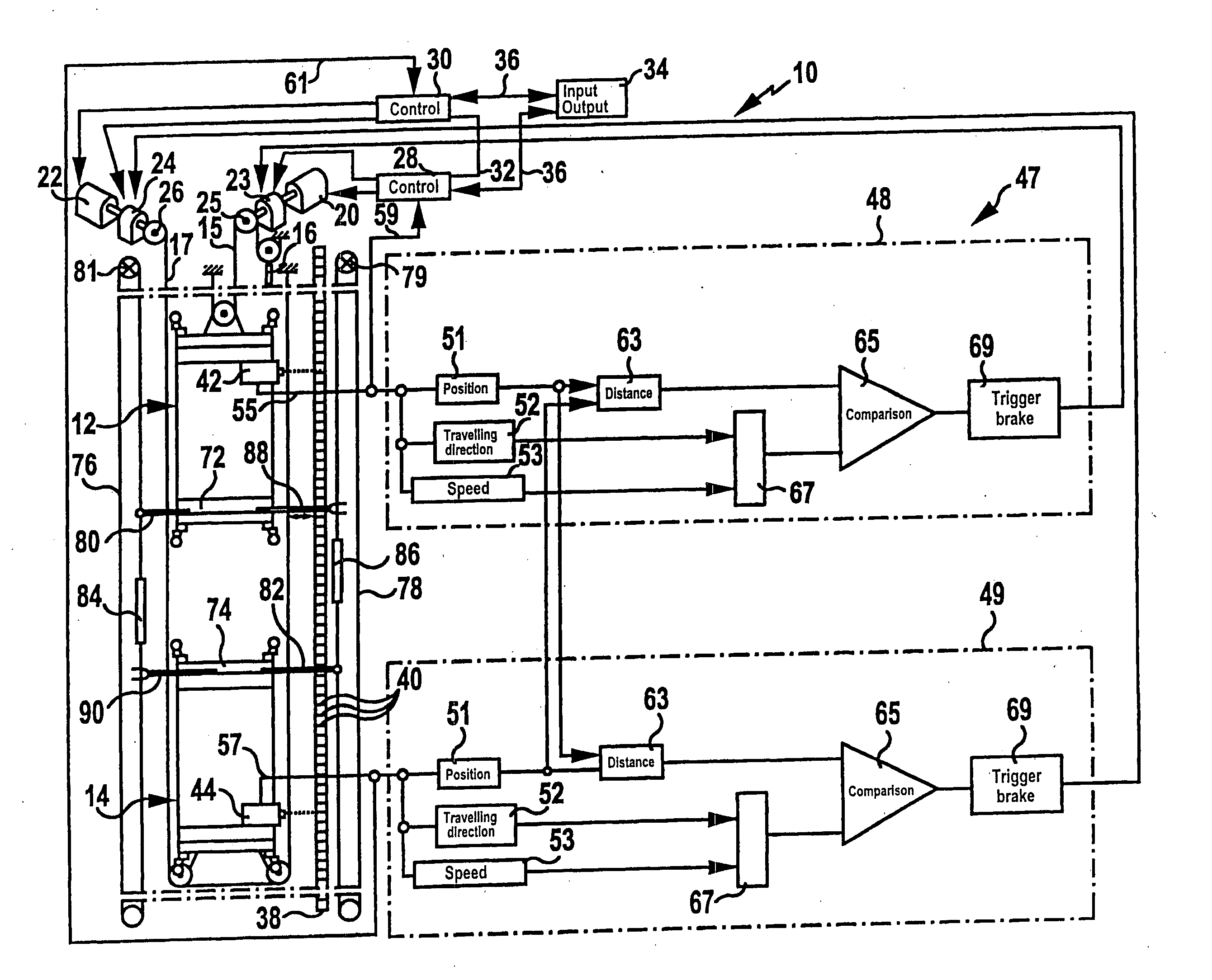
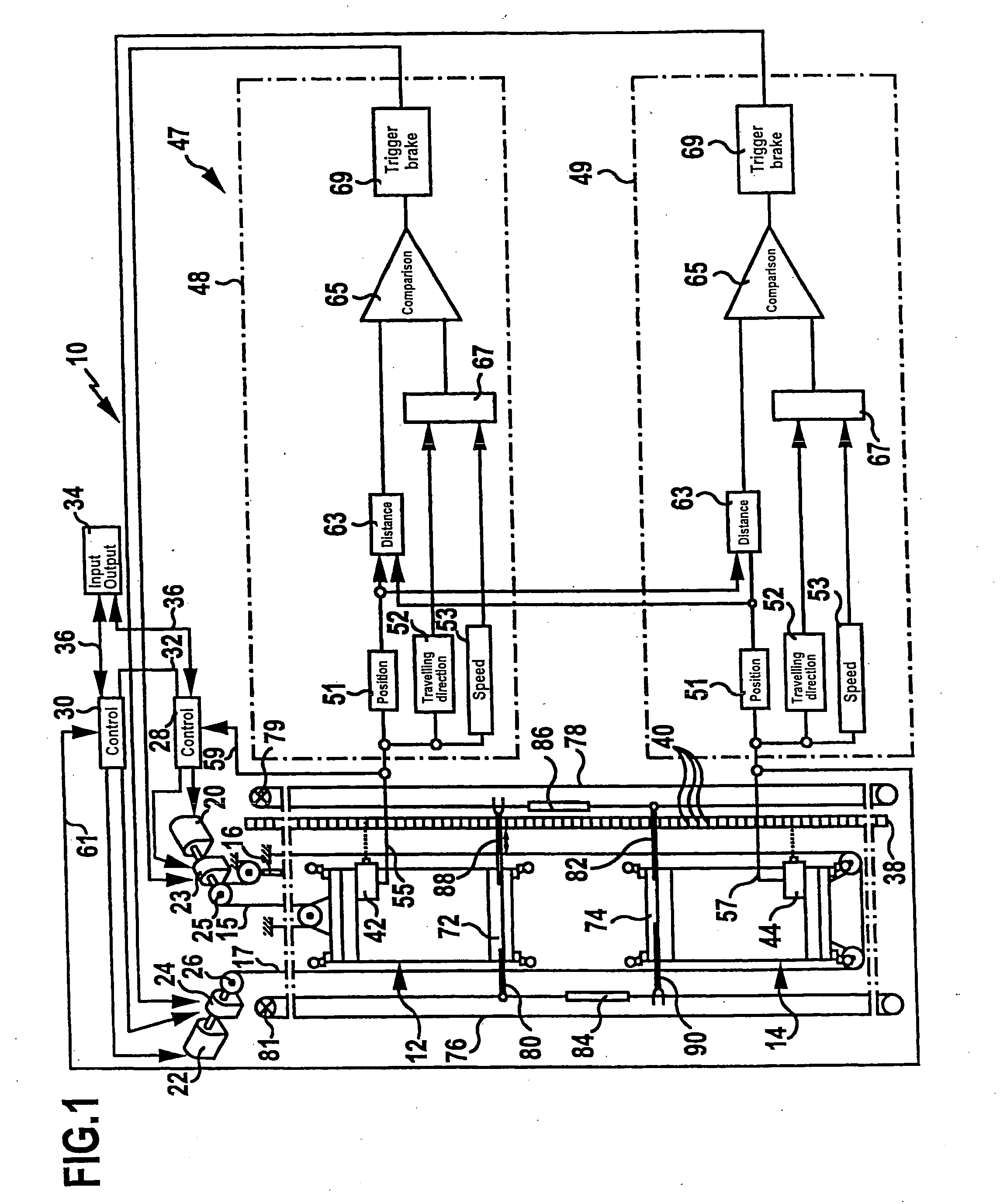
[0056] In FIG. 1, an elevator system according to the invention is represented in a greatly schematized form and provided overall with the reference numeral 10. The elevator system 10 comprises two cars 12, 14, which are disposed one above the other in a shaft (not represented in the drawing) and can be made to move up and down along a common traveling path, which is known per se and therefore not represented in the drawing. The car 12 is coupled to a counterweight 16 via a suspension cable 15. The car 14 is held on a suspension cable 17, which interacts in a way corresponding to the suspension cable 15 with a counterweight, which however is not represented in the drawing, in order to achieve a better overview.

[0057] Each car 12, 14 has an associated separate drive in the form of an electric drive motor 20 and 22, respectively, and in each case a separate brake 23 and 24, respectively. The drive motors 20, 22 in each case have an associated traction sheave 25 and 26, respectively, o...

second embodiment

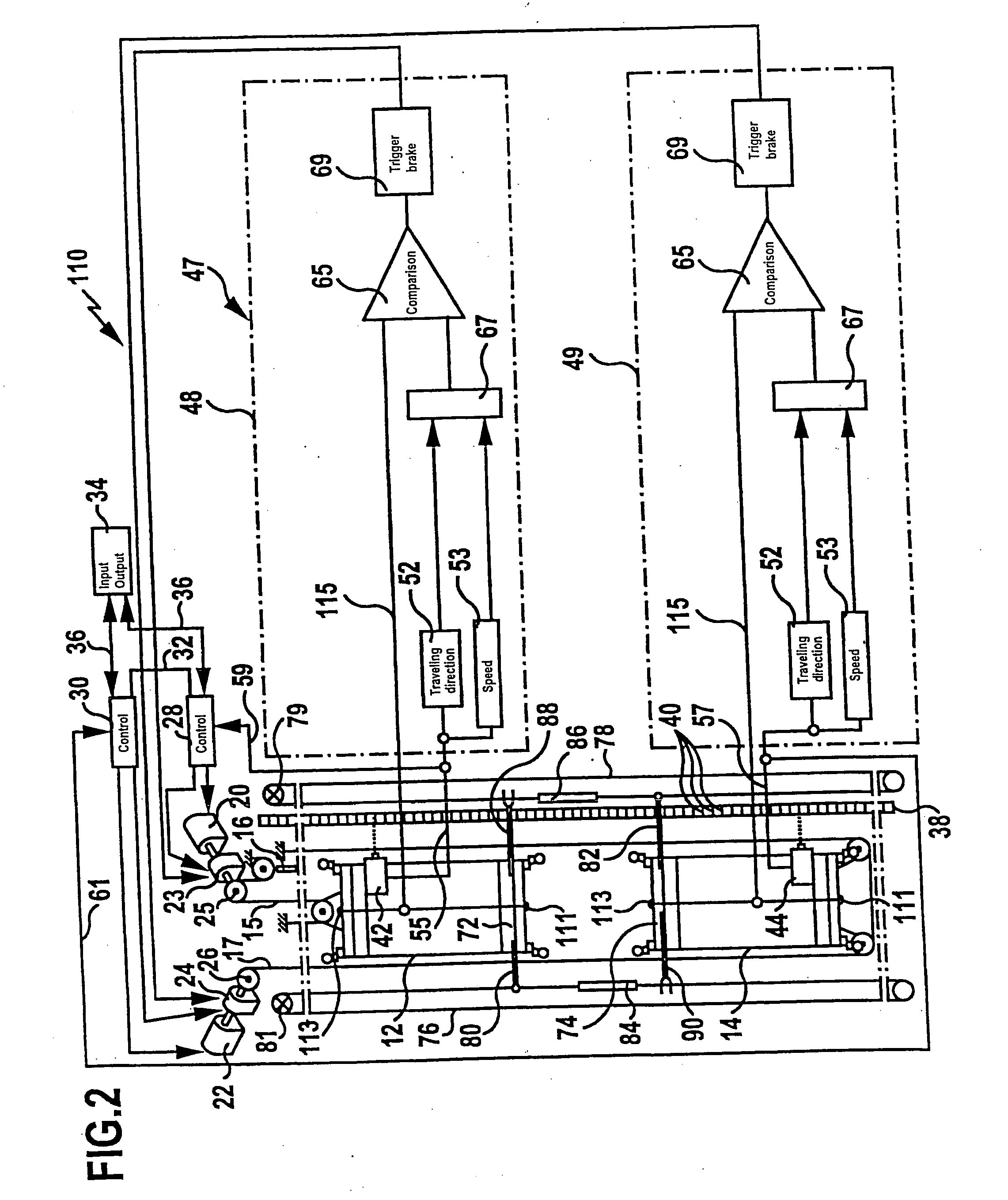
[0072] an elevator system according to the invention is represented in a greatly schematized form in FIG. 2 and provided overall with the reference numeral 110. The elevator system 110 is constructed largely identically to the elevator system 10 explained above with reference to FIG. 1. Identical components are therefore designated by the same reference numerals as in FIG. 1 and reference is made to the full content of the above with regard to the construction and function of the components.

[0073] The elevator system 110 differs from the elevator system 10 only in that the real distance which the two cars 12, 14 assume from each other is not ascertained electronically by means of a distance determining unit on the basis of the information provided by the barcode readers 42 and 44, but instead the distance between them is registered independently of the barcode readers 42 and 44 by contactless distance sensors 111 and 113 disposed on the upper side and underside of the cars 12 and 14...

third embodiment

[0075] In FIG. 3, the elevator system according to the invention is represented and provided overall with the reference numeral 210. This is once again constructed largely identically to the elevator system 10 explained above with reference to FIG. 1. Identical components are therefore also designated by the same reference numerals as in FIG. 1 in the case of the embodiment represented in FIG. 3 and reference is likewise made to the full content of the above with regard to the construction and function of the components.

[0076] The elevator system 210 represented in FIG. 3 differs from the elevator system 10 only in that the triggering of the safety gears 72 and 74, respectively, of the cars 12 and 14 is not performed mechanically by means of actuating sleeves and associated pivot arms fixed to speed governor cables, but instead the safety gears 72 and 74 are electronically triggered by the respectively associated safety units 48 and 49 if the two cars 12 and 14 approach each other i...


PUM


Abstract

The invention relates to an elevator system with at least one shaft, in which at least two cars can be made to travel along a common traveling path, and also with a shaft information system for determining the positions and speeds of the cars, which is connected to an electrical safety device. In order to develop the elevator system in such a way that a high handling capacity can be achieved with constructionally simple means, while reliably preventing car collisions, it is proposed according to the invention that an emergency stop of at least one car is triggerable independently of the control units by means of the safety device if the distance between a first car and a second car or an end of the traveling path goes below a preselectable critical distance, and that the safety gear of at least one car is triggerable if the distance which this car assumes from the neighboring car or an end of the traveling path goes below a preselected minimum distance, the control units of at least all the cars of one traveling path being connected to one another and altogether forming a group control device.

Description

[0001] This application is a continuation of international application number PCT / EP2002 / 012538 filed on Nov. 9, 2002. [0002] The present disclosure relates to the subject matter disclosed in international application number PCT / EP2002 / 012538 of Nov. 9, 2002, which is incorporated herein by reference in its entirety and for all purposes.BACKGROUND OF THE INVENTION [0003] The invention relates to an elevator system with at least one shaft, in which at least two cars can be made to travel along a common traveling path, the cars respectively comprising a safety gear and the cars respectively having an associated control unit, a drive and a brake, and also with a shaft information system for determining the positions and speeds of the cars, which is connected to an electrical safety device. [0004] In an effort to achieve a high handling capacity with the smallest possible overall volume for elevator systems, it has already been proposed to configure the elevator systems in such a way th...

Claims


Application Information

Patent Timeline
Patent Type & Authority Applications(United States)
IPC IPC(8): B66B1/14B66B1/24B66B5/00B66B9/00
CPCB66B5/0031B66B11/0095B66B9/00B66B5/005B66B5/00
Inventor REUTER, GUENTERMEISSNER, WOLFGANGSCHLECKER, HELMUTNUEBLING, WALTERTHUMM, GERHARD
Owner TK ELEVATOR INNOVATION & OPERATIONS GMBH
Why Eureka
Try Eureka