Systems and methods for operating an electromagnetic actuator

a technology of electromagnetic actuators and circuits, applied in the direction of magnets, program control, road transportation emission reduction, etc., can solve problems such as incomplete combustion

Inactive Publication Date: 2005-12-22
COMBUSTION DYNAMICS
View PDF4 Cites 49 Cited by
  • Summary
  • Abstract
  • Description
  • Claims
  • Application Information

AI Technical Summary

Problems solved by technology

Further, FIG. 4 depicts certain ideally targeted or aimed or purposed injection events (e.g., hampered by unstably controlled injection shot duration and dwell interval) and...

Method used


Image

  • Systems and methods for operating an electromagnetic actuator
  • Systems and methods for operating an electromagnetic actuator
  • Systems and methods for operating an electromagnetic actuator

Examples


Embodiment Construction

[0053] As required, detailed embodiments of the present invention are disclosed herein; however, it is to be understood that the disclosed embodiments are merely illustrative of the invention that may be embodied in various forms. In addition, each of the examples given in connection with the various embodiments of the invention are intended to be illustrative, and not restrictive. The figures are not necessarily to scale, some features may be exaggerated to show details of particular components. Therefore, specific structural and functional details disclosed herein are not to be interpreted as limiting, but merely as a basis for the claims and as a representative basis for teaching one skilled in the art to variously employ the present invention.

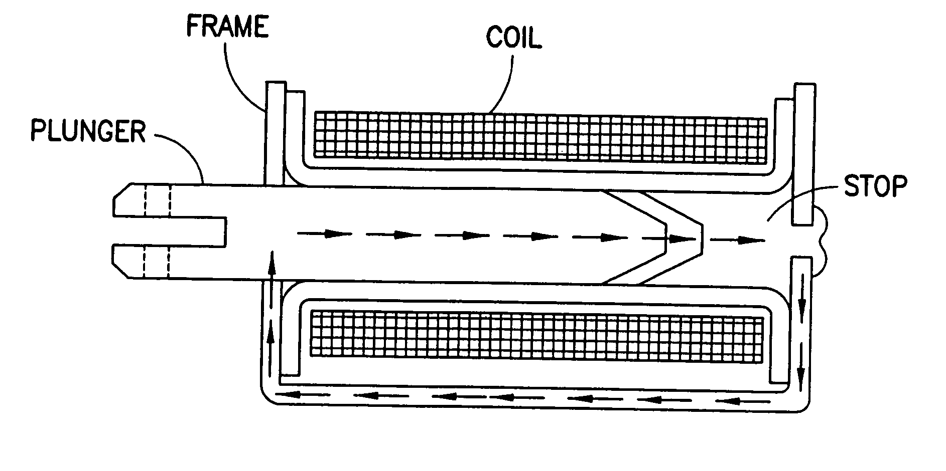
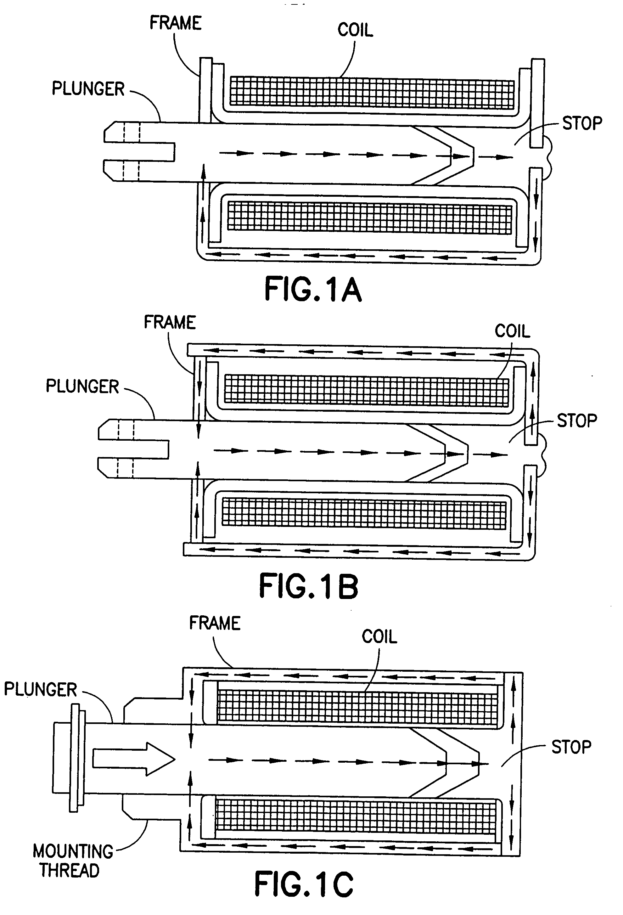
[0054] In summary, various embodiments of the present invention relate to electromagnetic actuators used to control fuel injectors in internal combustion engines, linear solenoids, and other electromagnetic devices (e.g., which convert ele...


PUM


Abstract

One embodiment of the present invention relates to a method for constructing a circuit for controlling an electromagnetic actuator. Another embodiment of the present invention relates to a method for designing a circuit for controlling an electromagnetic actuator.

Description

CROSS-REFERENCE TO RELATED APPLICATIONS [0001] This application is a continuation-in-part of U.S. application Ser. No. 10 / 389,183, filed Mar. 14, 2003 and is a continuation-in-part of U.S. application Ser. No. 10 / 634,436, filed Aug. 5, 2003. This application also claims the benefit of U.S. Provisional Application Ser. No. 60 / 589,892, filed Jul. 21, 2004. Each of these three applications is incorporated herein by reference in its entirety.FIELD OF THE INVENTION [0002] One embodiment of the present invention relates to a method for constructing a circuit for controlling an electromagnetic actuator. [0003] Another embodiment of the present invention relates to a method for designing a circuit for controlling an electromagnetic actuator. [0004] For the purposes of the present application the term “physically remote” (e.g., in the context of a coil being physically remote from an electromagnetic actuator) is intended to refer to the fact that the electromagnetic actuator and the coil may...

Claims


Application Information

Patent Timeline
IPC IPC(8): B05B1/30B05D1/00F02D1/06F02D41/20F02D41/40F02M45/08F02M47/02F02M51/06F02M57/02F02M59/36
CPCF02D41/20F02D41/402F02D2041/2013F02D2041/2072F02D2041/2079F02D2041/288Y02T10/82F02M51/061F02M57/02F02M59/366F02M2200/24H01F2007/1855Y02T10/44F02M45/08Y02T10/40
Inventor ISMAILOV, MURAD M.
Owner COMBUSTION DYNAMICS
Why Eureka
Try Eureka